5 module status 5.1 gpi alarm and control, Module status outputs and selection of inputs, 5 module status – Nevion SDI-CHO-2x1-PB User Manual
Page 9
SDI-CHO-2x1/ SDI-CHO-2x1-PB
Rev. E
nevion.com | 9
5 Module status
The status of the module can be monitored in three ways.
1. GYDA System Controller (optional).
2. GPI at the rear of the sub-rack.
3. LED’s at the front of the sub-rack.
Of these three, the GPI and the LED’s are mounted on the module itself, whereas the
GYDA System Controller is a separate module giving detailed information on the card
status. The functions of the GPI and the LED’s are described in sections 5.1 and 5.2.
The GYDA controller is described in a separate user manual.
5.1 GPI ALARM and Control
– Module Status Outputs and
selection of inputs
These outputs can be used for wiring up alarms for third party control systems. The
GPI outputs are open collector outputs, sinking to ground when an alarm is triggered.
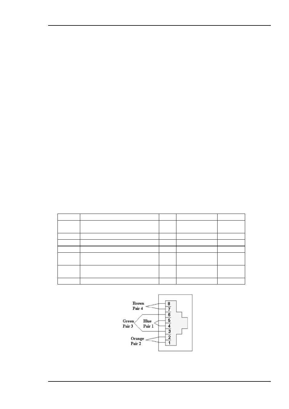
The GPI connector is shown in figure 7.
The two GPI inputs can be used to control switching of inputs.
Electrical Maximums for GPI outputs
Max current: 100mA
Max voltage: 30V
SDI-CHO-2X1 module GPI pinning:
Signal Name
Pin # Mode
Direction
Status
General error status for the
module.
Pin 1 Open Collector Output
LOS
Loss Of Signal at selected input Pin 2 Open Collector Output
Input 1 Input 1 selected (IN1)
Pin 3 Open Collector Output
Input 2 Input 2 selected (IN2)
Pin 4 Open Collector Output
Reset
Reset selected input to main
Pin 5 TTL, 0V =
active level
Input
Set
Set selected input to standby
Pin 6 TTL, 0V =
active level
Input
Ground 0 volt pin
Pin 8 0V.
Figure 7 - GPI Pin layout