4 operation 4.1 gpi alarm, Module status outputs, 4operation – Nevion DA-VA User Manual
Page 8: 1 gpi alarm – module status outputs
DA-VA
Rev. H
nevion.com | 8
4
Operation
The status of the module can be monitored in three ways.
1. GYDA System Controller (optional)
2. GPI at the rear of the sub-rack
3.
LED’s at the front of the sub-rack.
Of these three, the GPI and the LED’s are mounted on the module itself, whereas the
GYDA System Controller is a separate module giving detailed information on the card
status. The functions of the GPI and the LED are described in sections 5.1 and 5.2.
The GYDA controller is described in a separate user manual.
4.1 GPI ALARM
– Module Status Outputs
Only available when using the standard
–C1 backplane
These outputs can be used for wiring up alarms for third party control systems. The
GPI outputs are open collector output, sinking to ground when an alarm is triggered.
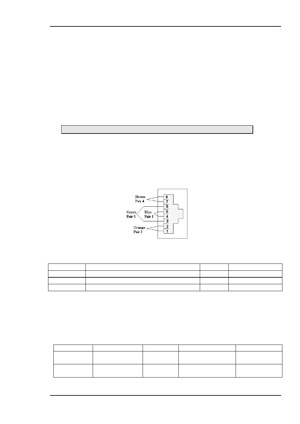
The GPI connector is shown in figure 4.
Electrical Maximums for GPI outputs
Max current: 100mA
Max voltage: 30V
Figure 4: GPI pin out
DA-VA module GPI pinning:
Signal
Name
Pin #
Mode
Status
General error status for the module.
Pin 1
Open Collector
Signal
Signal detected (HW revision 3 only)
Pin 2
Open collector
Ground
0 volt pin
Pin 8
0V.
4.2 Front Panel - Status Monitoring and Signal Detection
The status of the module can be monitored visually at the front of the front of the
module.
The DA-VA has one LED showing the status. The hardware revision 2 of the DA-VA
has also a built in detector for signal monitoring. When signal is present, LED is green,
otherwise it will be red. The LEDs are described in the following table:
Diode \ state
Red LED
Yellow LED
Green LED
No light
Status
Module is faulty
Module is OK
Module power is OK
Module has no
power
Signal
No signal detected
Signal present
Module has no
power