Norsat 25W ATOM User Manual
Page 20
ATOM 25W/40W/50W
Revision 1.1
908239
20
908239_r1.1 - Operator Manual ATOM KU
25-40-50W.doc
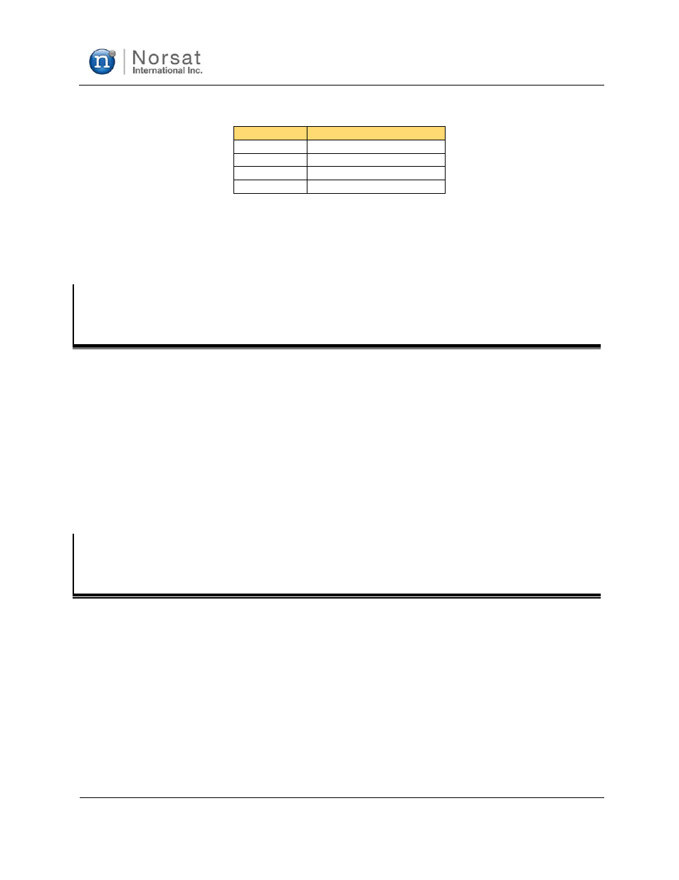
Table 2-4: J3 Connector Pin Out
Pin
Name
A
Ground or V-
B V+
C V+
D
Ground or V-
Positive voltage is applied to pins B and C (connected internally). Negative voltage is applied to pins A
and D (connected internally).
Pins A and D are connected internally to case ground.
Section 2.6
J4
–
RF
OUTPUT
The output is a standard WR75 or WR62 square waveguide. Specify which flange is to be installed at
time of order. Both types of flanges have a groove for an O-ring seal, which is highly recommended to
keep moisture out of the unit.
Also, for outdoor installations, after bolting the waveguide-to-waveguide connection, it is recommended to
add RTV silicone compound as a sealant around the entire perimeter of the joint where the flanges meet.
This will provide extra protection against water ingress at the flange-to-flange interface.
The unit is supplied with two screw lengths (four 6-32x3/8" and four 6-32x7/16"); it is the users
responsibility to ensure that the appropriate length of screw is used. There should be at least 4 threads of
engagement (0.125") with the holes in the waveguide flange.
Section 2.7
G
ROUND
C
ONNECTION
The unit is supplied with a 10-32 screw and internal tooth lock washers for grounding purposes. It is
highly recommended that the unit is grounded according to national and local electrical codes before use.