4 mode control (aa38-7xx and aa38-8xx) – Northern Airborne Technology AA38-5xx User Manual
Page 14
AA38-5xx, -6xx, -7xx and -8xx Series Local ICS Loop
SM54 Installation and Operation Manual
Section 2 Rev: 1.00
Issue 4
Page 2-5
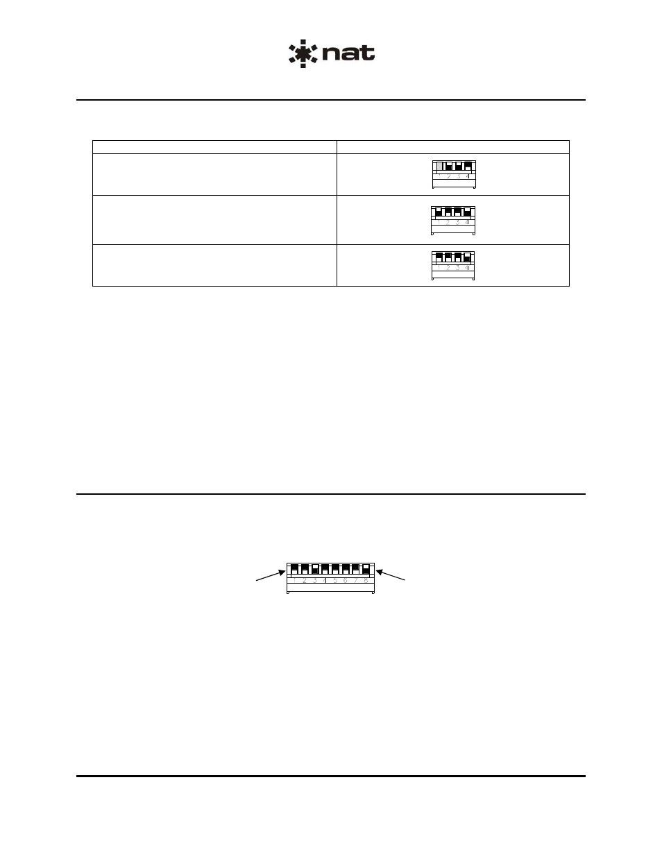
Tie Line Mode selection is accomplished by setting the Mode Control switch as shown in Figure 3 below.
TIE LINE MODE Selection
Switch Position
ANDREA Tie Line
3 NAT Tie Lines (Default)
4 NAT Tie Lines
Figure 3: Tie Line Mode Selection
Andrea Tie Line
Switch 2 and 3 closed (down)
Switch 4 open (up)
Switch 1 has no effect
3 NAT Tie Line
Switch 1 and 4 closed (down)
Switch 2 and 3 open (up)
4 NAT Tie Line
Switch 4 closed (down)
Switch 1, 2 and 3 open (up)
Note: All other switch combinations are invalid.
2.5.4
Mode control (AA38-7xx and AA38-8xx)
The AA38-7xx and AA38-8xx mode control is used in the same way as the AA38-5xx and -6xx models,
but is an 8-position switch accessible through the left side of the unit. To open a switch, place it in the ‘up’
position and to close it put it in the ‘down’ position as shown in Figure 4.
Switch 1 shown in the
open (up) position.
Switch 8 shown in the
closed (down) position.
Figure 4: Mode Control DIP Switch
ENG-FORM: 805-0115.DOT
CONFIDENTIAL AND PROPRIETARY TO NORTHERN AIRBORNE TECHNOLOGY LTD.