4 controls and indicators, 1 built-in tests (bits), 2 faceplate illumination – Northern Airborne Technology ACP53-001 User Manual
Page 23
ACP53-001 DACS Audio Control Panel
SM75 Installation and Operation Manual
Section 3 Rev: 1.00
Issue 1
Page 3-2
ENG-FORM: 806-0113.DOT
CONFIDENTIAL AND PROPRIETARY TO NORTHERN AIRBORNE TECHNOLOGY LTD.
3.4
Controls and Indicators
Note: For visual confirmation of the following tests, the ACP53 mode control must be in the NORM
position, and the Transmit selector switch must be set to select a transceiver (i.e. in any position
other than ICS).
3.4.1
Built-In Tests (BITs)
3.4.1.1
Power-Up Built-In Test (PBIT)
On power-up, the ACP53 runs a PBIT to confirm correct operation of the unit. When power is first applied,
all indicators will illuminate for a period of approximately 3 seconds.
If the ACP53 has not established connection to other units in the communications management system
three seconds after the power is applied, the ACP53 indicators will extinguish until connection is achieved.
3.4.1.2
Continuous Built-In Test (CBIT)
The ACP53 requires serial communication with the communications management system (for example
the Northern Airborne Technology Ltd AMU50). If serial communications is lost for more than 0.5 seconds,
all the ACP53 indicators will extinguish and remain off until communication is re-established.
3.4.2
Faceplate Illumination
TX
ICS
ICS
RX
ICS
MIN
PTT
PRESET
VOX
EMER
BK-UP
NORM
ISO
CALL
TX
ICS
ICS
RX
ICS
MIN
PTT
PRESET
VOX
EMER
BK-UP
NORM
ISO
CALL
ISO
CALL
TX
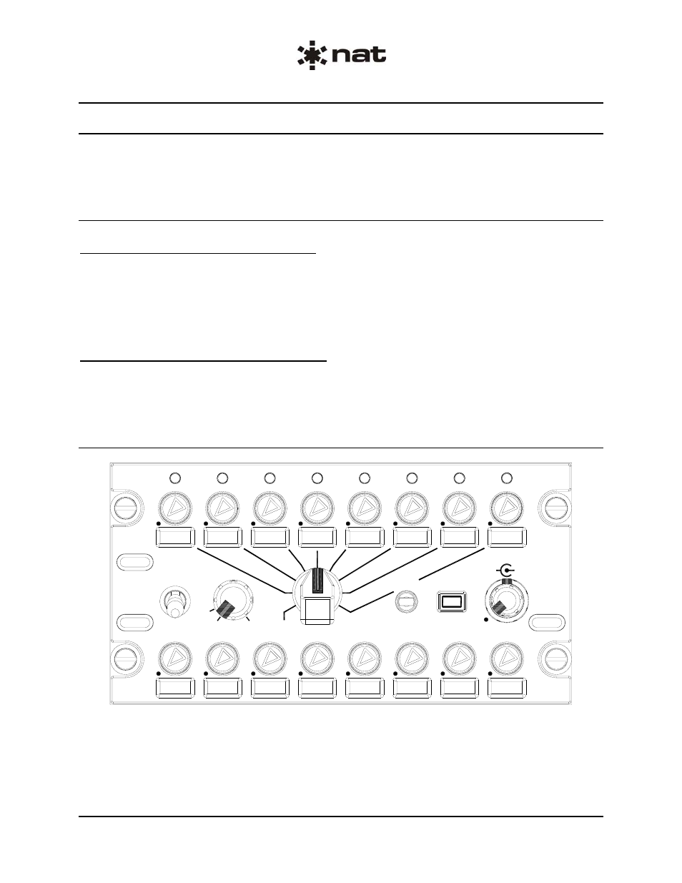
ACP53-001 faceplate with blank legends.
The illumination of the ACP53 faceplate is linked to the aircraft dimming buss.
When backlighting is off, there is no faceplate illumination other than Transmit Access indicators (see
section 3.4.3). When backlighting is on, all knobs and legends illuminate to a level proportional to the
aircraft dimming buss level.