4 mechanical installation, 5 electrical installation, 6 pin assignment – Northern Airborne Technology 247 User Manual
Page 8
Model 247 Audio Mixing Amplifier
SM247 Installation and Operation Manual
Section 2 Rev: 1.00
Issue 2
Page 2-3
ENG-FORM: 805-0118.DOT
CONFIDENTIAL AND PROPRIETARY TO NORTHERN AIRBORNE TECHNOLOGY LTD.
2.4.4
Mechanical Installation
The Model 247 is designed to be mounted in virtually any pressurized or unpressurized location within an
aircraft fuselage. The unit can be mounted in any axis using four (4) #8 mounting screws. No shock or
vibration isolators are required.
The Model 247 must be mounted to a clean metal surface which is electrically bonded to the aircraft
ground plane. The unit is finished with a coating which prevents corrosion. This film is electrically
conductive and should not be removed for electrical bonding.
2.4.5
Electrical Installation
The Model 247 has 3 separate power and ground inputs for each of its 3 internal mixer circuits. This is
designed to allow maximum flexibility for the installer if separate power supplies are used. All three
power and ground inputs can also be connected together and supplied from one source. Maximum
current draw for each mixer circuit within the Model 247 is 0.5 Amps assuming maximum output voltage
into a maximum load of 8 ohms.
2.4.6
Pin Assignment
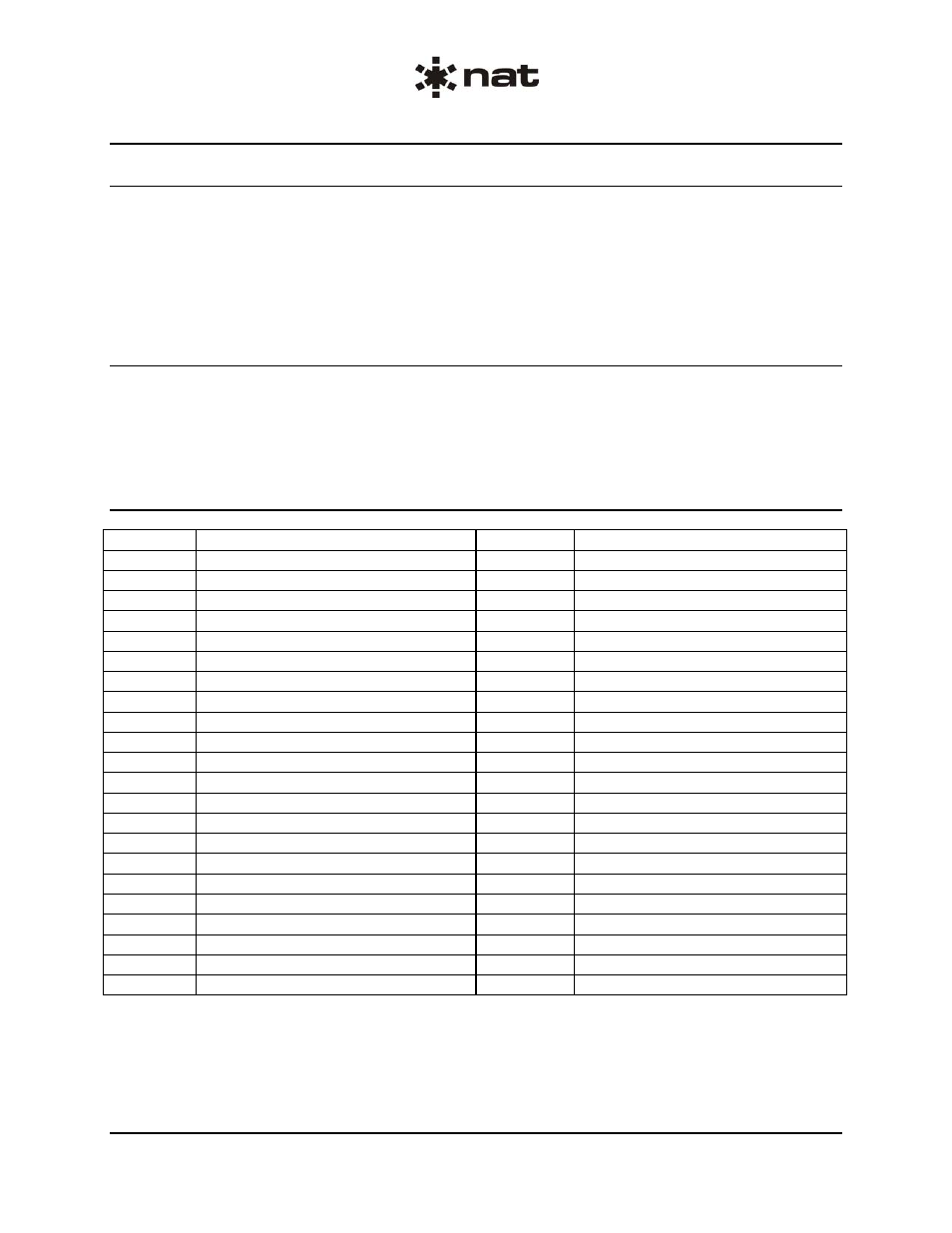
Pin Assignment
Pin Assignment
P40-1
Mixer 1, Input 1 HI
P40-2
Mixer 1, Input 2 HI
P40-3
Mixer 1, Input 3 HI
P40-4
Mixer 1, Input 4 HI
P40-5
Mixer 1, 28 VDC
P40-6
Mixer 2, Input 1 HI
P40-7
Mixer 2, Input 2 HI
P40-8
Mixer 2, Input 3 HI
P40-9
Mixer 2, Input 4 HI
P40-10
Mixer 2, 28 VDC
P40-11
Mixer 3, Input 1 HI
P40-12
Mixer 3, Input 2 HI
P40-13
Mixer 3, Input 3 HI
P40-14
Mixer 3, Input 4 HI
P40-15
Mixer 3, 28 VDC
P40-16
Mixer 1, Input 1 LO
P40-17
Mixer 1, Input 2 LO
P40-18
Mixer 1, Input 3 LO
P40-19
Mixer 1, Input 4 LO
P40-20
Mixer 1, Power Return
P40-21
Mixer 2, Input 1 LO
P40-22
Mixer 2, Input 2 LO
P40-23
Mixer 2, Input 3 LO
P40-24
Mixer 2, Input 4 LO
P40-25
Mixer 2, Power Return
P40-26
Mixer 3, Input 1 LO
P40-27
Mixer 3, Input 2 LO
P40-28
Mixer 3, Input 3 LO
P40-29
Mixer 3, Input 4 LO
P40-30
Mixer 3, Power Return
P40-31
Chassis Ground(shield ground)
P40-32
Chassis Ground (shield ground)
P40-33
Chassis Ground(shield ground)
P40-34
Mixer 1, Output LO
P40-35
Mixer 1, Output HI
P40-36
Chassis Ground (shield ground)
P40-37
Chassis Ground(shield ground)
P40-38
Chassis Ground (shield ground)
P40-39
Mixer 2, Output LO
P40-40
Mixer 2, Output HI
P40-41
Chassis Ground(shield ground)
P40-42
Chassis Ground (shield ground)
P40-43
Mixer 3, Output LO
P40-44
Mixer 3, Output HI