Olson Technology 6920-RT-x User Manual
Page 6
025-370516 REV X2
Page 6
INTERNAL ADJUSTMENTS AND TEST POINTS
There are no internal test points and no internal adjustments that would normally be performed in the field. The backup RF and
status monitoring options require some internal changes. Due to the variety of these that are available, please consult Olson
Technology. CAUTION: removing the cover allows access to static sensitive components. These operations should be per-
formed only at a static controlled location.
REVERSE INPUT RF LEVEL SETTING
The return RF level should be set using the reverse pad on the 6920 main board. The internal pad in the return transmitter is for
laser OMI matching, not for level setting. Monitor the –20db test point on the transmitter and adjust the reverse pad on the 6920
main board for the correct level from the RF drive table for the transmitter type being used.
RECOMMENDED RF DRIVE LEVEL
Laser Transmitter Option
RF Input
RF Input –20db Test Point
6920-RT-2-302/2mW (FP)
+20dBmV / Chan
0 dBmV / Chan
6920-RT-5-304/2mW (DFB)
+27.5dBmV / Chan
+7.5dBmV / Chan
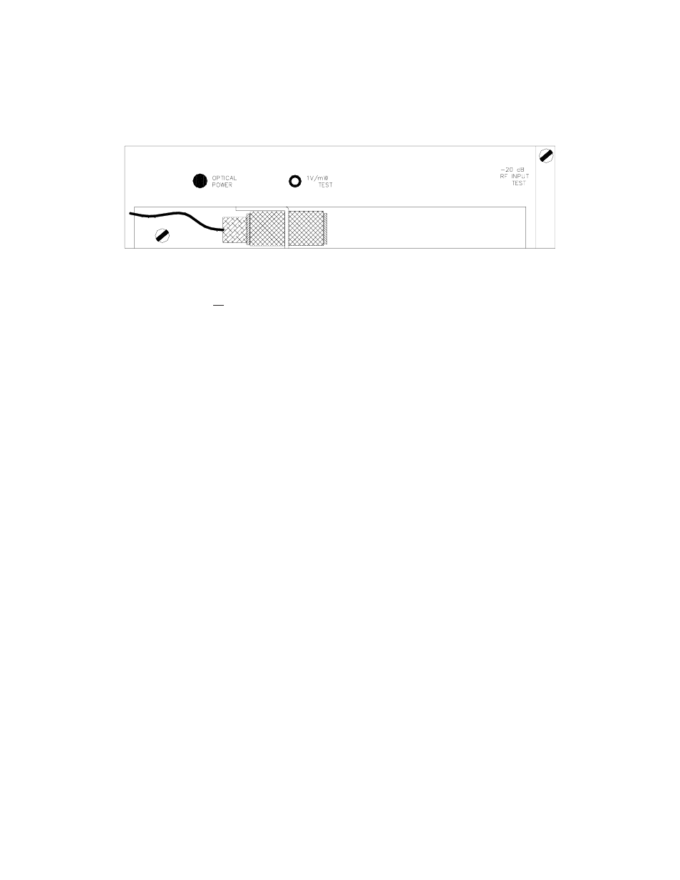
EXTERNAL ADJUSTMENTS AND TEST POINTS
There are no external adjustments. There is one test point that monitors optical output power. This is scaled to 1V/mW and
should be measured with a high impedance voltmeter. There is a red/green LED that will be green when the laser optical output
power is OK and red if it is out of spec. There is a -20 dB return RF input test point which is normally accessed through the
outside of the housing using a type ‘G’ connector.