Olson Technology FRMUC-AR440 User Manual
Page 5
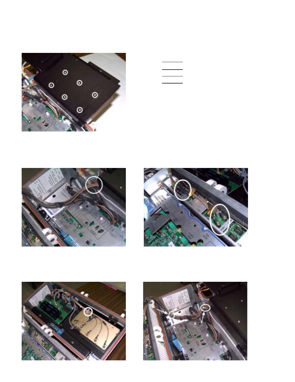
Step 4: Install the upconverter onto the top of the metal tray using the 6 screws which attach from the under side as
shown and tighten firmly (See Figure 5). Plug the transmitter cable assembly from SWITCHED IN into the RF
OUT port on the upconverter
Step 6: The RF cables can now be zip tied into place. There is a white cable hold down, place the RF cables into
this, and slide one of the supplied zip ties through the two slots in the hold down, and around the cables, tighten until
snug (Figure 9). The RF cables are then secured to the wirering harness where shown. (Figure 10)
Figure 5:
Figure 6:
Step 5: Feed the RF cables through the slot between the top tray and the main housing as shown (Figure 7). The
cables are marked on each end to show where they connect. (Figure 6) Example: A cable marked with 2 and 3, will
connect to band 2 on the upconverter, and port 3 on the P7RCM module (Figure 8).
Figure 7:
Figure 8:
Figure 9:
Figure 10:
025-000477 REV x1
Page 5
Up-Converter
Band 1
Band 2
Band 3
Band 4
P7RCM Module
Port 1
Port 3
Port 4
Port 6