Olson Technology NTM342x User Manual
Page 5
025-370527 REV X1
Page 5
ALIGNMENT PROCEDURE
The NTM-324x optical transmitter’s OMI has been optimized with an RF input level of +3.0dBmV per carrier (Six analog carriers)
maximum loading at the transmitters input. Do to the number of different configurations offered for the HLN-384x node, the
amount of loss through the node can vary by a substantial amount. Therefore transmitter drive levels should be set via the -10dB
test point.
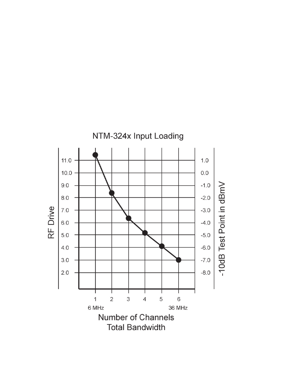
The chart below shows what drive levels are required for a given number of channels or QAM/QPSK loading. The units are setup
at the factory for an input level of +3dBmV per carrier with six carrier loading at the transmitter input. The level going into the
node will vary depending on the nodes configuration.
For Example, if the transmitter is going to be loaded with three video channels, than the test point needs to be approximately
-3.75dBmV per carrier. This level can be attained by changing the RF input PAD on the transmitter module. Increasing the PAD
value will lower the RF input level, while decreasing it will raise the RF input level.
If QAM, QPSK, or similar digital loading is being used, than the loading is calculated by total bandwidth rather than the number
of channels. If loading from 5 to 25MHz, than the input level will be set for 20MHz of total bandwidth. The chart below shows us
that 20MHz of bandwidth is equivalent to approximately 3.5 video channels, or an RF test point level of -4.25dBmV per channel.