Olson Technology OTD-3000-I User Manual
Page 4
025-000390 REV B
Page 4
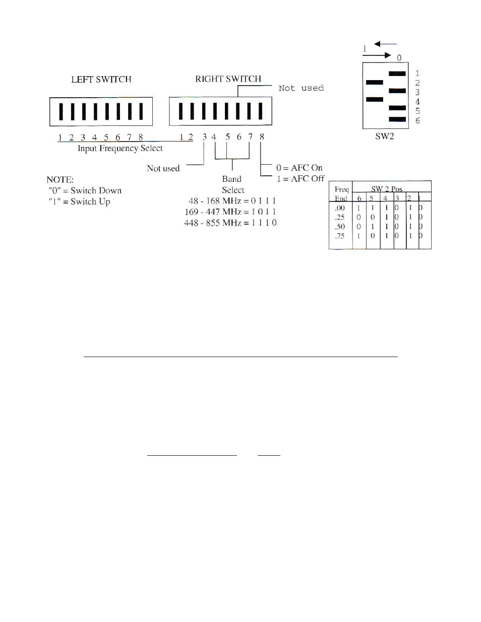
Figure 1 - DIP SWITCH FUNCTIONS
Positions 1 through 8 of the left switch and positions 1 and 2 of the right switch select the input frequency in 1MHz
increments. At the right switch, positions 4, 5 and 7 select the proper frequency band for the input tuner and position
8 switches the AFC feature on and off. Positions 3 and 6 are not used.
COMPUTING SWITCH SETTINGS FOR NON-STANDARD FREQUENCIES
Positions 1 through 8 of the left switch and positions 1 and 2 of the right switch each have numerical values as shown
in figure 2 below. Each switch position is either UP = OFF = (value) or is DOWN = ON = 0. The TOTAL SWITCH
VALUE is the sum of these individual values and set the frequency in 1MHz steps.
LEFT SWITCH RIGHT SWITCH
Switch position 1 2 3 4 5 6 7 8 1 2
Value up 1 2 4 8 16 32 64 128 256 512
Value down 0 0 0 0 0 0 0 0 0 0
i.e.: 115 = 1 + 2 + 16 + 32 + 64
Figure 2 - DIP SWITCH VALUES