Olson Technology OTR-3550-SW User Manual
Page 8
Advertising
025-000232 REV C
Page 8
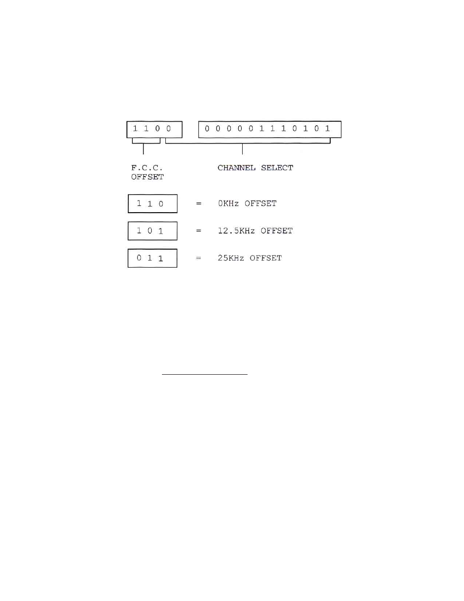
4) OUTPUT CHANNEL SELECTION - MODULATOR
Remove the front panel plate marked “Output Channel Select” to expose the channel select and offset
select DIP switches as shown in Figure #4. See page 11 for Modulator switch codes.
Figure #4
OUTPUT CHANNEL SELECT
A) Select the desired channel by use of the channel select switch and the code sheets.
2)
Select the proper offset by use of the offset switch and the offset information below.
3)
The example above indicates channel 6 with 0kHz offset.
Offset Select Information
1)
Channels A, B, C, L to W, AA to EE & GG to QQ = 12.5KHz.
2)
Channels A-2, A-1 & FF = 25KHz.
3)
All others = 0KHz.
Advertising
See also other documents in the category Olson Technology TV Accessories:
- 6920-RT-x (7 pages)
- LLRX-400 (Arris) (6 pages)
- 7-OR (10 pages)
- SA6940-RT (8 pages)
- DSK-300-S (9 pages)
- FRMUC-AR440 (7 pages)
- LLRX-200 (Arris) (7 pages)
- DSK-550 (11 pages)
- FRMUC-T-6940 (7 pages)
- NTM342x (5 pages)
- ISX-3040 (6 pages)
- LCD-550x1 (13 pages)
- LCM-300-S (10 pages)
- LCM-500-550-BG (6 pages)
- LCM-500-550 (5 pages)
- LCM-550x1 (FAC) (3 pages)
- LCM-550x1 (PAL B/G) (4 pages)
- LCM-500-550-DF (6 pages)
- LCM-550x1 (PAL I) (4 pages)
- LCM-550x1 (11 pages)
- LCM-600 (6 pages)
- LCM-6550 (6 pages)
- LCx12-AMP (3 pages)
- LCM-750x3 (8 pages)
- LCP-500-550 (10 pages)
- LP-PS-X (11 pages)
- LP-DC-X (10 pages)
- LP-OA (7 pages)
- LP-OT-RCxx (7 pages)
- LP-OR-304 (10 pages)
- LP-penis (21 pages)
- OLMT (9 pages)
- OLRT (8 pages)
- Penis (27 pages)
- OTA-1000 (5 pages)
- OT-1000-HH Rev.X4 (20 pages)
- OTD-3000-BG (8 pages)
- OTD-3000 (12 pages)
- OTM-3000 (PAL D) (7 pages)
- OT-1000-HH Rev.X2 (24 pages)
- OTDC-440-X (2 pages)
- OT-DCM-F (6 pages)
- OTD-3000-I (9 pages)
- OTDL-FOM-01 (6 pages)
- LCM-550x1-Series (50 pages)