Vav/zone controllers, Vav/zone damper/airfl ow setpoints, Smts ii technical guide – Orion System System Manager TS II In-House User Manual
Page 67
SMTS II Technical Guide
VAV/Zone Controllers
67
VAV/Zone Damper/Airfl ow Setpoints
Damper/Airfl ow Setpoints
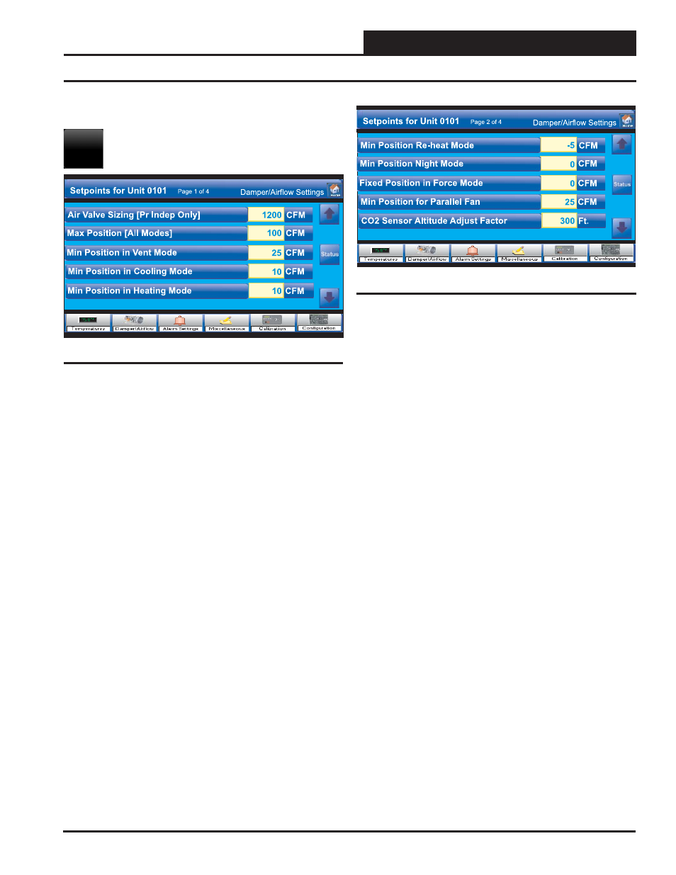
Touch the
< Damper/Airflow>
button to access the
Damper/Airfl ow Setpoint Screens.
Air Valve Sizing [Pr Indep Only]
If this is a Pressure Independent Box, enter the manufacturer’s airfl ow
constant (fl ow coeffi cient) at 1” water gauge for the duct diameter this
box is mounted on. High limit = 9999 CFM; Low limit = 0 CFM
Max Position [All Modes]
The VAV/Zone controller will not allow the damper or airfl ow calcula-
tion to exceed the Maximum setpoint while it is allowing the damper
to modulate. Enter the maximum damper or airfl ow setting used by all
modes of operation. Pressure Independent = CFM. Pressure Dependent
= %. High limit = 9999 CFM / 100%; Low limit = 0 CFM / 0%
Min Position in Vent Mode
During Vent Mode when there is no heating or cooling demand, the
damper or airfl ow will maintain at least the Vent Minimum amount
of airfl ow into the zone for ventilation. Enter the minimum damper or
airfl ow setting used during Supply Air Vent Mode of operation. Pressure
Independent = CFM. Pressure Dependent = %. High limit = 9999 CFM
/ 100%; Low limit = 0 CFM / 0%
Min Position in Cooling Mode
During Supply Air Cooling Mode, if the space being served by this
damper is satisfi ed and has no cooling demand, the damper will close
to this Cool Minimum setting. This provides a minimum amount of
airfl ow into the space for ventilation, even if the space does not require
additional cooling. Enter the minimum damper or airfl ow setting used
during Supply Air Cooling Mode of operation. Pressure Independent =
CFM. Pressure Dependent = %. High limit = 9999 CFM / 100%; Low
limit = 0 CFM / 0%
Min Position in Heating Mode
During Supply Air Heating Mode, if the space being served by this
damper is satisfi ed and has no heating demand, the damper will close to
this Heat Min setting. This provides a minimum amount of airfl ow into
the space for ventilation, even if the space does not require additional
heating. Enter the minimum damper or airfl ow setting used during supply
air heating mode of operation. Pressure Independent = CFM. Pressure
Dependent = %. High limit = 9999 CFM / 100%; Low limit = 0 CFM / 0%
Damper
Min Position Reheat Mode
Enter the minimum damper or airfl ow setting used during the Space
Reheat Mode of operation. Pressure Independent = CFM. Pressure De-
pendent = %. High limit = 9999 CFM / 100%; Low limit = 0 CFM / 0%
Min Position Night Mode
Enter the minimum damper or airfl ow setting used during unoccupied
hours. The Night Min is the position the damper will move to when the
system is in Override Mode and this particular damper is not part of the
override group. This Night Min position only affects non-fan powered
boxes. Pressure Independent = CFM. Pressure Dependent = %. High
limit = 9999 CFM / 100%; Low limit = 0 CFM / 0%
Fixed Position in Force Mode
Many times while troubleshooting a system, it is useful to have the zone
damper set to a specifi c damper position or airfl ow setting. This setpoint
can be used to determine where the damper/airfl ow will remain when
the VAV/Zone Controller receives a Force to Fixed Position command.
Enter the fi xed damper or airfl ow setting used by the fi xed position
force mode during the morning warm-up. Pressure Independent = CFM.
Pressure Dependent = %. High limit = 9999 CFM / 100%; Low limit
= 0 CFM / 0%
Min Position for Parallel Fan
Enter the minimum damper or airfl ow setting used to activate the parallel
fan if installed. Pressure Independent = CFM. Pressure Dependent = %.
High limit = 9999 CFM / 100%; Low limit = 0 CFM / 0%
CO2 Altitude Adjust Factor
Enter the distance above sea level for the installed Carbon Dioxide Sen-
sor. Altitude correction is required for valid readings if you are above
500 feet. High limit = 15,000 feet; Low limit = 0 feet 500 feet. High
limit = 15,000 feet; Low limit = 0 feet
Figure 130: Damper/Airfl ow Setpoints Screen 1
Figure 131: Damper/Airfl ow Setpoints Screen 2