7 system view, Front view – input connectors and indicator lights – QVidium QVMP2C-1011 User Manual
Page 7
User’s Manual v.28
QVidium™ MPEG2+4 Codec
1.7 System View
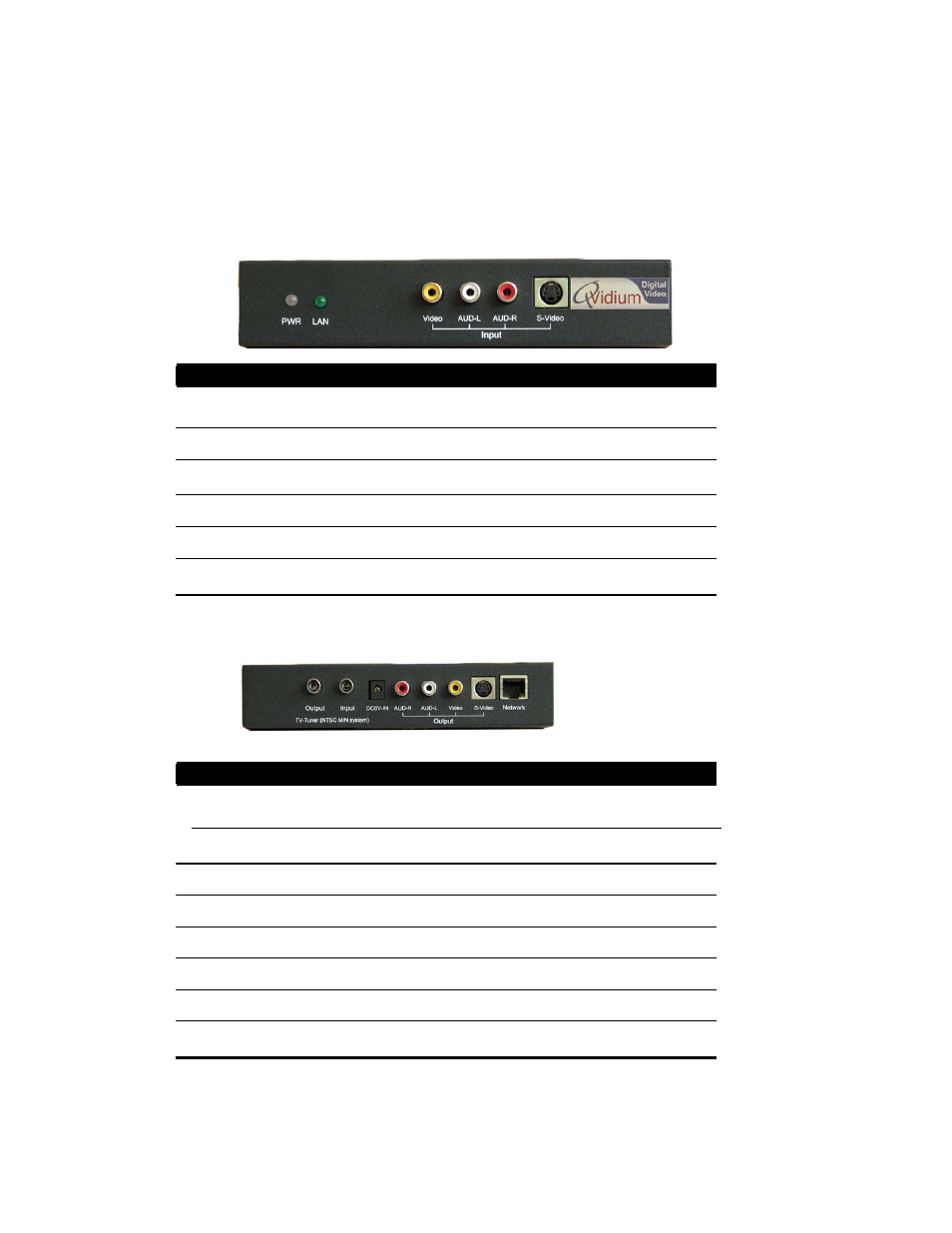
Front View – Input connectors and Indicator Lights
7 of 45 - Copyright 2007-2008 QVidium™ Technologies, Inc.
Ref Component
Description
1 Power Indicator
Glows green when the power is on.
2 LAN Indicator
Indicates connectivity/activity on 10/100 Ethernet port.
3 Composite Video Input for NTSC or PAL composite video signal.
4 Left Audio
Line input for left stereo audio channel.
5 Right Audio
Line input for right stereo audio channel.
6 S-Video
Input for NTSC or PAL S-Video input.
Rear View – Output Connectors, Ethernet Port, & TV Tuner Connectors
Ref Component
Description
1 TV-Tuner Output
Pass-through connector from TV-Tuner Input.
2 TV-Tuner Input
RF input for cable-TV or Off-the Air feed.
3 DC Power
DC power adaptor input. (6V/2A)
4 Right Audio Output Right audio output channel.
5 Left Audio Output
Left audio output channel.
6 Composite Video
Composite video output (PAL/NTSC).
7 S-Video Output
S-Video video output (PAL/NTSC).
8 10/100 Ethernet
RJ-45 port for Fast Ethernet network connection.