Remko kwl (h) – REMKO KWL 130 H User Manual
Page 20
KWL 130(H) -
220(H)
KWL 270(H) -
320(H)
KWL 370 (H)
A
350
350
800
B
1500
800
800
C
600
800
800
D
350
800
800
E
500
1800
1800
Warm air
Cold
Fresh air
Light
well
Chiller
Warm air
Light
well
Additional
Fan
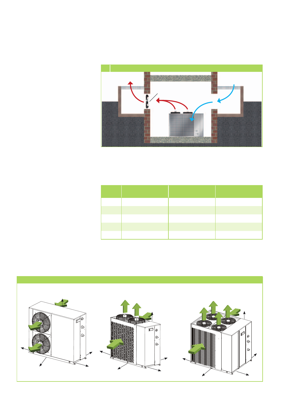
5 Installation inside buildings (cooling mode)
Minimum clearances
E
C
B
A
D
E
C
B
A
D
E
C
B
A
D
KWL 130(H) - 220(H)
KWL 270(H) - 320(H)
KWL 370 (H)
Minimum clearances
The following illustration indicates
the minimum clearances for trou-
ble-free operation of the system.
These protection zones serve to
ensure unrestricted air intake and
discharge, as well as providing suf-
ficient room for performing main-
tenance and repairs and prevent-
ing the unit from being damaged.
■
Comply with any regulations
and conditions affecting the
structure of the building. If
necessary, use sound reducing
material.
All values in mm
REMKO KWL (H)
20