Electrical wiring diagram clk 170-rv – REMKO CLK 80-RV User Manual
Page 19
Advertising
19
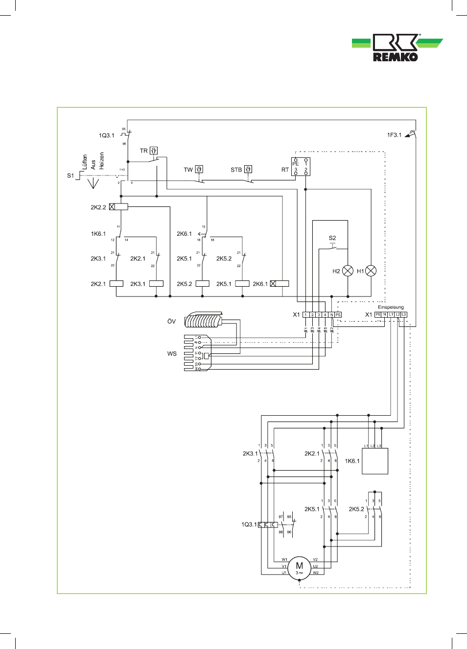
Electrical wiring diagram CLK 170-RV
Load circuit
Control circuit
Legend:
S1 = Operating switch
S2 = Reset button (burner)
H1 = Operating lamp (green)
H2 = External burner fault lamp (red)
TR = Temperature controller
TW = Temperature monitoring device
STB = Safety temperature limiter
X1 = Terminal block
M = Fan motor
WS = Burner connector, 7-pole
RT = Thermostat receptacle
ÖV = Multiflex oil pre-heating
1F3.1 = Controller fuse
2K2.1 = Mains fuse
2K2.2 = Time relay
2K3.1 = Mains fuse
2K5.1 = Delta contactor
2K5.2 = Star contactor
1K6.1 = Phase sequence relay
2K6.1 = Star-delta relay
1Q3.1 = Motor overload protection switch
We reserve the right to modify the dimensions and design as part of the ongoing technical development process.
Advertising
This manual is related to the following products: