Technical data, Electrical wiring diagram – REMKO ELT 9-6 User Manual
Page 11
11
Technical data
1)
Noise measurement DIN 45635 - 01 - KL 3
R1 bis R3
R4 bis R6
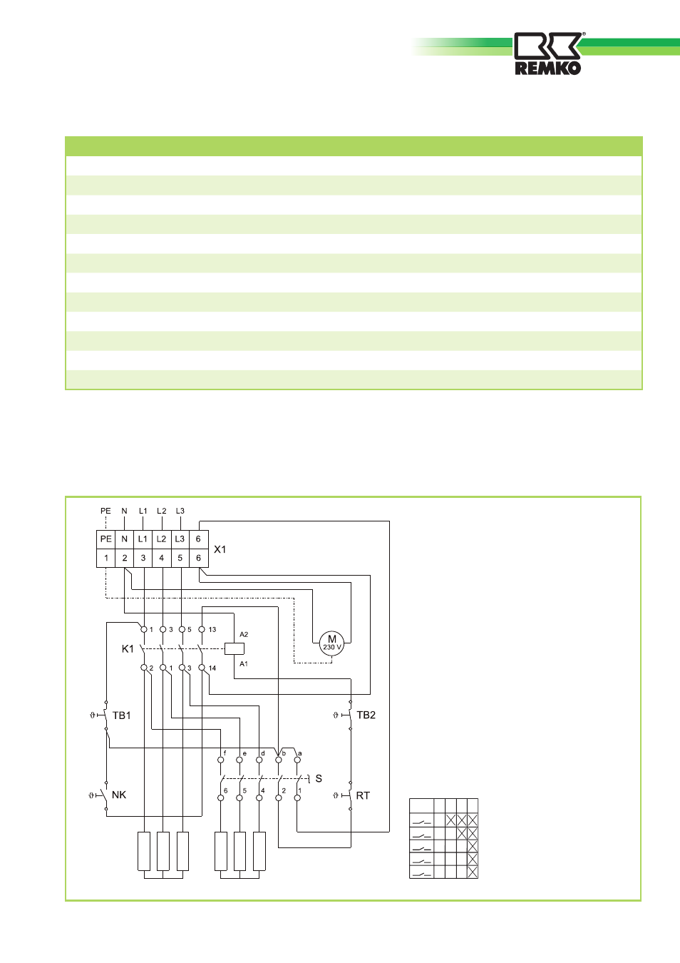
Legend:
K1
= Contactor
M
= Motor
NK
= Cooling thermostat
R1 to R3 = Heating resistors for setting 1
R4 to R6 = Heating resistors for setting 2
RT
= Thermostat
S
= Operating switch
TB1
= Temperature limiter
TB2
= Temperature limiter
X1
= Terminal strip
Electrical wiring diagram
We reserve the right to make changes in dimensions and design in the interest of technical advances.
a
d
e
f
b
1
2
4
5
6
S 0 1 2 3
Switching level for operating switch [S]
Series
ELT 9-6
Nominal heat output
kW
9.0
Switchable heat output
kW
2 x 4.5
Air capacity
m3/h
600
Power supply
V/Hz
400/3~N/50
Max. nominal current
A
13.2
Max. power input
kW
9.7
Fuse protection (local)
A (slow-acting)
16
Sound pressure level L
pA
1m
1)
dB (A)
53
Dimensions:
Length
mm
510
Width
mm
300
Height
mm
455
Weight
kg
14.7