Remko pww, Unit dimensions – REMKO PWW Series User Manual
Page 34
Advertising
34
REMKO PWW
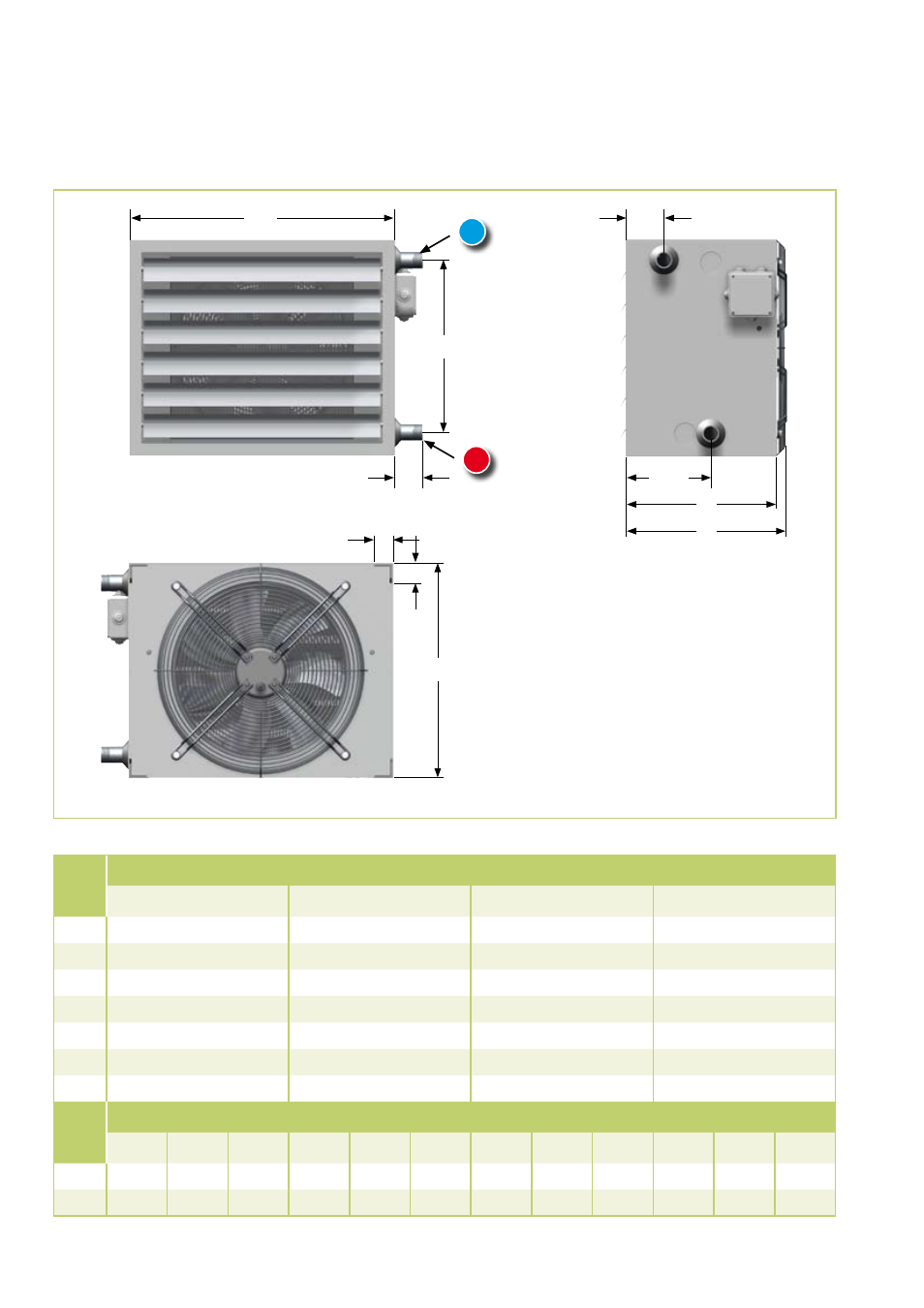
Unit dimensions
Dim.
in
mm
Unit type
PWW 30
PWW 50
PWW 80
PWW 100
A
560
640
800
880
B
440
515
630
740
C
360
360
360
390
D
403
406
412
452
E
344
419
534
644
F
80
80
80
80
G
45
45
45
45
Dim.
in
Inch
Unit type
30-2
30-3
30-4
50-2
50-3
50-4
80-2
80-3
80-4
100-2 100-3 100-4
V
R ¾“
R 1“
R 1¼“ R ¾“
R 1“
R 1¼“
R 1“
R 1¼“ R 1¼“ R 1¼“ R 1½“ R 1½“
R
R ¾“
R 1“
R 1¼“ R ¾“
R 1“
R 1¼“
R 1“
R 1¼“ R 1¼“ R 1¼“ R 1½“ R 1½“
We reserve the right to make changes to dimensions and design in the interest of technical advances.
A
B
G
C
E
F
167
98
D
G
V
= Water inlet (flow)
R
= Water outlet (return)
V
R
The water inlet (flow) is always at the
“BOTTOM
”
.
Even if the units are turned during
installation and connected from the
other side.
Advertising