Remko cmf / cmt, Hydraulic connection – REMKO CMF-80 v.2 User Manual
Page 14
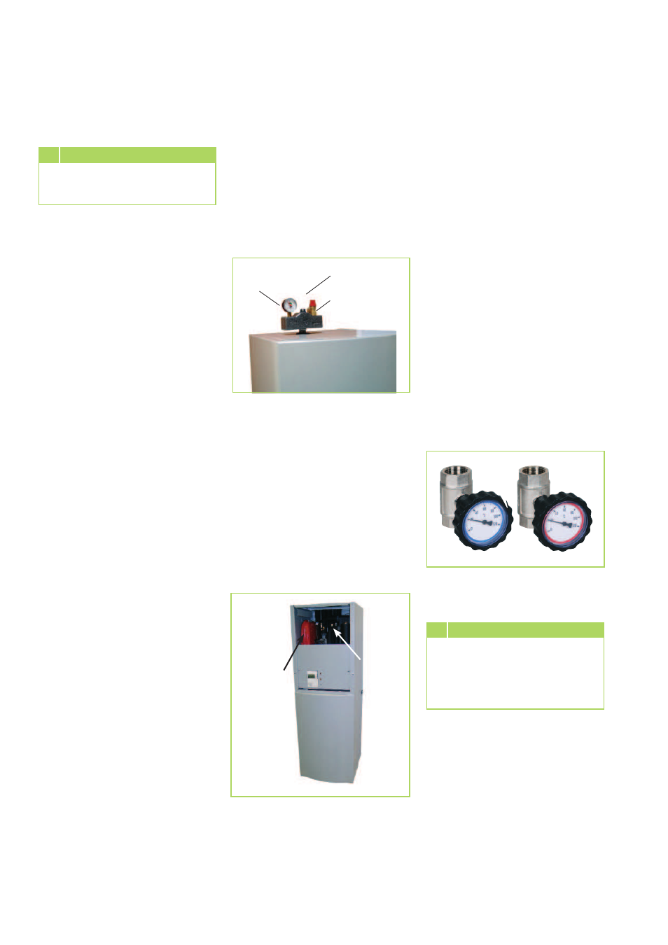
REMKO CMF / CMT
Safety valve
Automatic deaerator
Manometer
Indoor unit
Hydraulic connection
Turning the thermometer
heads serves to close or open
the stop valves!
CAUTION
■
For models CMF 80, CMF 90
and CMT 100 it must be en-
sured that the condenser pump
fl ow rate always amounts to
1,400 l/h. For models CMF 140,
CMF 150 and CMT 150 the
fl ow rate must amount to 2,200
l/h. The indoor module com-
ponents are designed for these
fl ow rates.
■
A hydraulic splitter or storage
tank is to be used in order to
separate the system circuits.
■
A pipeline network connection
must be undertaken before
installing the heat pump.
■
Floor heating systems must be
protected against excessively
high and low inlet tempera-
tures.
■
The pipe diameters for the
supply and return connections
of the heat pump may not be
reduced before the connection
of a system separation.
■
Air bleed valves and drain-off
taps must be planned for in
suitable areas.
■
The complete pipe network for
the system must be fl ushed be-
fore connecting the heat pump.
■
The safety module contained in
the scope of delivery comprises
of a manometer, air vent and
safety valve. It is to be mounted
on the pipe connection for the
indoor module.
■
An expansion vessel must be
designed for the entire hy-
draulic system. The expansion
vessel for the CMT range has a
volume of 12 litres and is only
intended to protect the stor-
age tank and not for the entire
pipe network of the hydraulic
system.
■
The system pressure of the
entire pipe network is to be
matched to the hydraulic sys-
tem and must be checked when
the heat pump is in a non-oper-
ative state.
■
In order to reduce the heating
cycles to a minimum, it must
be ensured that the heating
load from the heat pump is
fully transferred to the heating
system.
■
The supplied stop cocks are
to be positioned directly at
the connections for the heat
pump inlet and return lines. The
shut-off valves each contain a
thermometer with gauge.
■
The dirt traps should be in-
stalled outside of the heat
pump in the return line.
A separate installation must be
carried out for every system.
NOTE
Manual-
deaerator
Expansion-
vessel
14