RLE LD300 User Manual
Page 2
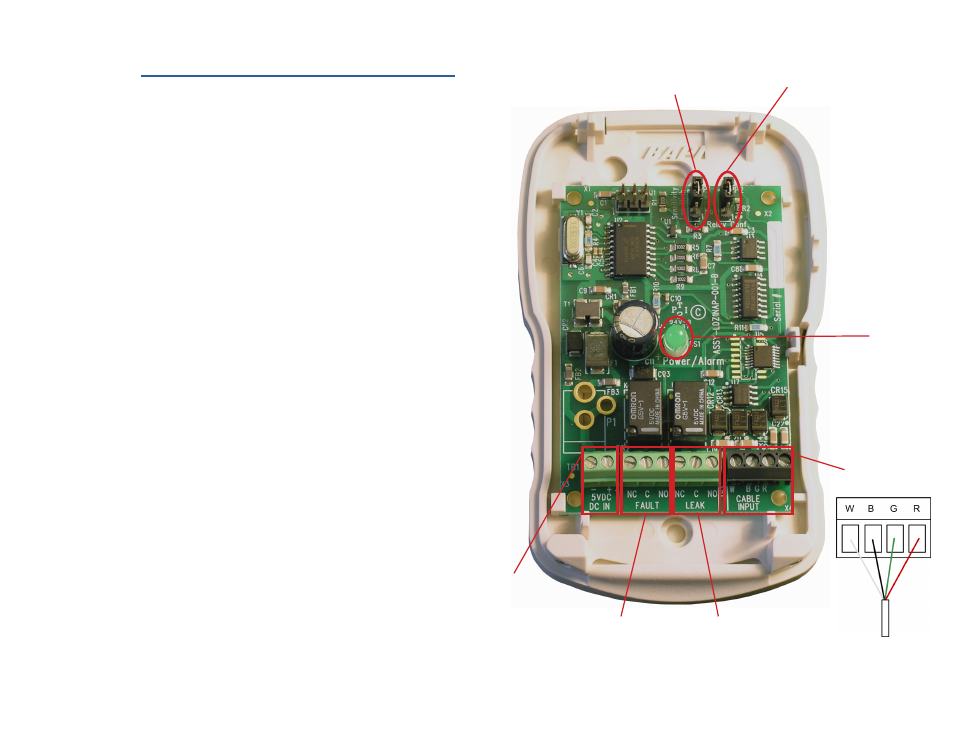
Leader Cable /
Sensing Cable Input
JP1
Leak Sensitivity
Top - Most sensitive
No Jumper - Medium sensitivity
Bottom - Least sensitive
5VDC
Power
Input
Cable Fault
Relay Output
Be sure the leader
cable is wired
into the correct
pinouts.
Leak
Relay Output
JP2
Relay Output Configuration
Top - Supervised
Bottom - Non-supervised
LED
Leak - The LED flashes constantly, one second on, one second off. This pattern
repeats itself as long as the leak is present.
Test the System
If the LD300 is already connected to a BMS or NMS, notify monitoring personnel
before you begin testing the system.
To verify the LD300’s functionality, test three points within the length of sensing
cable - one at the beginning, one in the middle of the length, and another near
the end of the length of cable.
There are a variety of ways to simulate a leak.
• Pour a small puddle of water on the cable while it rests on the floor.
• Dunk the cable in a cup of water.
• Wet a paper towel or rag and wrap it loosely around the cable. This is
popular if the cable is used in pipe applications. Be careful to wrap the wet
cloth loosely around the cable. Do not put pressure on the cable.
IMPORTANT - To avoid inaccurate readings, do not grip the cable with your
hand.
Remove all simulated leak sources and return the system to its normal operating
state.
To test the cable fault alarm, remove the end-of-line terminator (EOL) from
the end of the sensing cable. This will cause a cable break, which should be
reported appropriately by the LD300. Once the cable break alarm is verified,
reapply the EOL and ensure the system returns to its normal operating state.