Sensoray 953-ET User Manual
Page 12
Advertising
GPIO Connector: J3
Pin
Signal
Pin
Signal
1
GPO-E4
2
GPO-C4
3
GPI-C4
4
GPI-A4
5
GPO-E3
6
GPO-C3
7
GPI-C3
8
GPI-A3
9
GPO-E2
10
GPO-C2
11
GPI-C2
12
GPI-A2
13
GPO-E1
14
GPO-C1
15
GPI-C1
16
GPI-A1
17
Not Used *
18
Not Used *
Note:
*
Reserved for future use
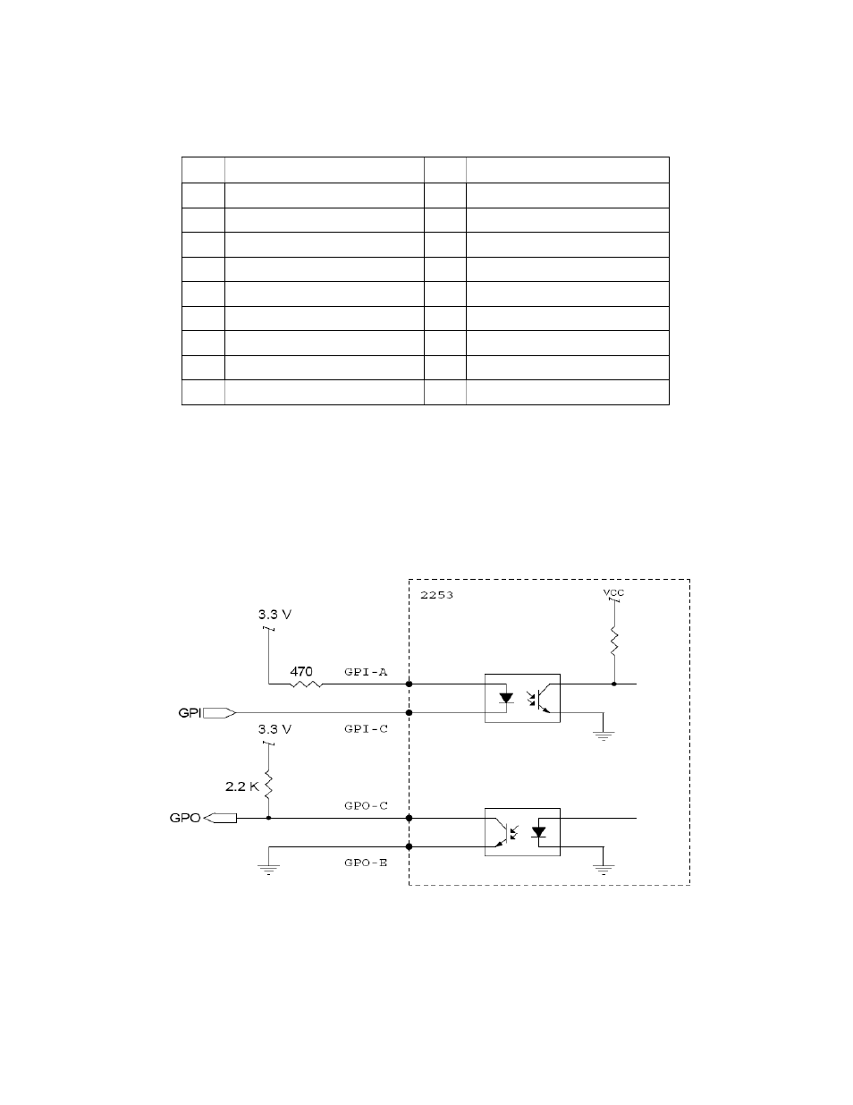
GPIO Connections
Model 953 provides one general purpose optoisolated input (GPI) and one general
purpose optoisolated output (GPO) per channel. A recommended connection circuit is
shown in Figure 1 below:
Figure 1. Optoisolated GPIO.
12
Advertising
See also other documents in the category Sensoray Hardware:
- 2226 (15 pages)
- 2253 (19 pages)
- 616 (8 pages)
- 516 AVStream DirectShow (10 pages)
- 2246 (42 pages)
- 2246 (50 pages)
- 2255 (33 pages)
- 614 (17 pages)
- 611 (7 pages)
- 314 (14 pages)
- 614 Caption Overlay (18 pages)
- 311 (9 pages)
- 314 Quick Start (14 pages)
- 1012 (12 pages)
- 810 Quick Start (7 pages)
- 911 (17 pages)
- 812 (16 pages)
- 810 (15 pages)
- 615 (8 pages)
- 615 (15 pages)
- 711 (36 pages)
- 609 (17 pages)
- 817 (11 pages)
- 817 (18 pages)
- 2411 (11 pages)
- 2250 (6 pages)
- 2263 (12 pages)
- 2263 (25 pages)
- 2480 (10 pages)
- 2453 (27 pages)
- 819 (11 pages)
- 516 (8 pages)
- 3011S (29 pages)
- 2444 (19 pages)
- 7429 (48 pages)
- 718 (22 pages)
- 518 (57 pages)
- 526 (29 pages)
- 526 (7 pages)
- 826 (76 pages)
- 2426 (17 pages)
- 721 (13 pages)
- 2410 (9 pages)
- 2600 (80 pages)