Sensoray 2453 User Manual
Page 6
Advertising
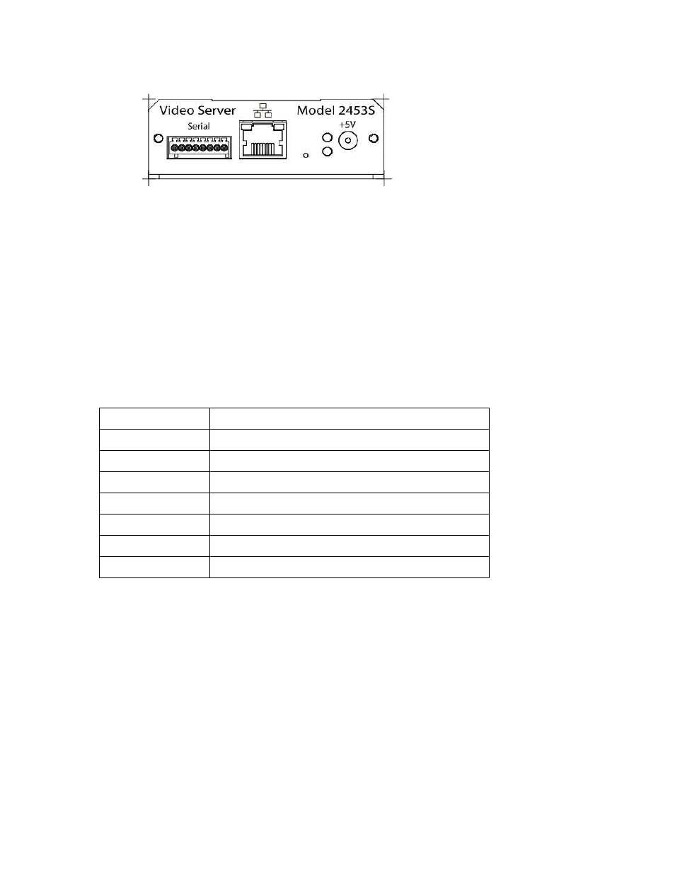
Left to right:
•
Serial interfaces (see Table 1 for pinout);
•
Ethernet;
•
Configuration button;
•
LED indicators: green (top) – power, red (bottom) – special function;
•
Power (5 V DC, + on center).
Table 1. Serial interfaces terminal block pinout (left to right):
1
RS-232 TX
2
RS-232 RX
3
Ground
4
Ground
5
RS-422 RX+
6
RS-422 RX-
7
RS-422 TX+
8
RS-422 TX-
Note: for RS-485 connect B (+) line to contact 5 or 7; A (-) line – to contact 6 or 8.
6
Advertising
See also other documents in the category Sensoray Hardware:
- 2226 (15 pages)
- 2253 (19 pages)
- 616 (8 pages)
- 516 AVStream DirectShow (10 pages)
- 2246 (42 pages)
- 2246 (50 pages)
- 2255 (33 pages)
- 614 (17 pages)
- 611 (7 pages)
- 314 (14 pages)
- 614 Caption Overlay (18 pages)
- 311 (9 pages)
- 314 Quick Start (14 pages)
- 1012 (12 pages)
- 810 Quick Start (7 pages)
- 953-ET (17 pages)
- 911 (17 pages)
- 812 (16 pages)
- 810 (15 pages)
- 615 (8 pages)
- 615 (15 pages)
- 711 (36 pages)
- 609 (17 pages)
- 817 (11 pages)
- 817 (18 pages)
- 2411 (11 pages)
- 2250 (6 pages)
- 2263 (12 pages)
- 2263 (25 pages)
- 2480 (10 pages)
- 819 (11 pages)
- 516 (8 pages)
- 3011S (29 pages)
- 2444 (19 pages)
- 7429 (48 pages)
- 718 (22 pages)
- 518 (57 pages)
- 526 (29 pages)
- 526 (7 pages)
- 826 (76 pages)
- 2426 (17 pages)
- 721 (13 pages)
- 2410 (9 pages)
- 2600 (80 pages)