Introduction, Implementing custom circuitry, Open thermocouple detection – Sensoray 7409TC User Manual
Page 2: Connections, Calibration
Introduction
Sensoray Models 7409TC and 7409TDIN are termination
boards that may be used to break out any 40-pin Smart A/D™
header connector onto screw terminals. Each of eight sensor
channels is allocated a dedicated, five-circuit, removable
terminal block.
Option shunts are provided to enable interruption of input signal
paths between header and screw terminals so that custom
circuitry may be inserted into the paths. A prototyping area,
consisting of an array of plated-through pads on 100-mil center
spacing, is provided for construction of custom circuitry.
Signal conditioning circuits (SCCs) are provided to facilitate
thermocouple open sensor detection. In addition, a calibrated
temperature sensor is provided for thermocouple compensation.
Model 7409TC is a circuit board assembly that includes all of
the features described above. Model 7409TDIN consists of a
7409TC assembly with integral DIN rail mounting hardware.
Implementing Custom Circuitry
As shown in the table to the
right, jumper posts E17
through E32 route the sense
leads of the eight terminal
blocks to the 40-pin header.
Shunts are factory installed at
all of these positions,
effectively bypassing the
prototyping area.
Remove these shunts to insert
custom circuits in the sense
signal path between the
terminal blocks and the header.
User-supplied custom circuits can be connected to header and
terminal block circuits by means of pads S1 through S50. Pad
S18 provides fused +12VDC power and S17 provides the 12V
return for powering custom circuitry. Refer to the schematic
diagram for details of pad wiring.
Open Thermocouple Detection
Two option shunts must be installed for each thermocouple
channel that requires open sensor detection.
For example, install shunts E7 and E8 to enable the SCC for
sensor channel 4.
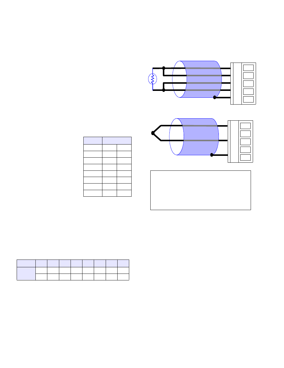
Connections
The following diagrams show how sensors are connected to the
TB. In both illustrations, the removable terminal block is shown
as viewed from the top.
Calibration
TB boards may be freely interchanged because their onboard
temperature sensors are calibrated. Although the sensor is
factory calibrated, it may be necessary to recalibrate it after
extended time in service or due to exposure to extraordinary
environmental stress.
Calibration Procedure
1.
Connect a calibrated Smart A/D™ to the TB. Connect a
calibrated thermocouple to the TB and immerse the “hot”
end into a precise, thermally controlled environment.
Allow at least ten minutes after power-up for the system to
warm up and stabilize.
2.
On the TB, adjust potiometer R6, then reset and re-initialize
the Smart A/D™ and read the thermocouple data.
3.
Repeat step 2 until the Smart A/D™ indicates the correct
thermocouple temperature.
Chan
0
1
2
3
4
5
6
7
Shunt
E15
E13
E11
E9
E7
E5
E3
E1
E16
E14
E12
E10
E8
E6
E4
E2
Chan
Jumpers
0
E15
E16
1
E13
E14
2
E11
E12
3
E9
E10
4
E7
E8
5
E5
E6
6
E3
E4
7
E1
E2
+V
+I
-V
-I
S
4-Wire Resistance Measurement
+V
+I
-V
-I
S
Thermocouple Measurement
RED
Important note for thermocouple users:
Exposing the TB to thermal transients can severely
degrade thermocouple measurement accuracy. If you
are measuring thermocouples, insulate the TB from air
flows such as ambient drafts and cooling fans. For
best results, encase the TB in a protective enclosure.