Jumper locations, Jp1 — local termination jumper, Rv2 — gain adjustment – Sierra Video UDA-8705A User Manual
Page 18: Leds
3-2
• User Controls
UDA-8705A User Manual (Rev. 1.1)
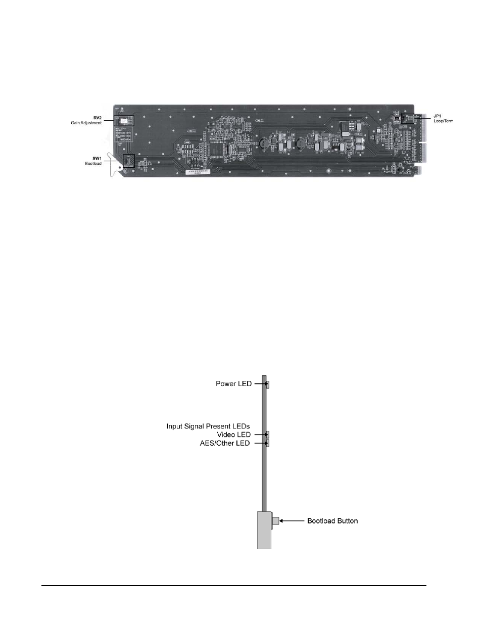
Jumper Locations
The following sections describe the jumpers on the UDA-8705A.
Figure 7. Jumper Locations
JP1 — Local Termination Jumper
The position of JP2 selects an optional 75ohm termination on the input of the UDA-8705A card.
Select one of the following options:
• TERM — Install the jumper in this position to terminate the input signal on this
card. This is the default setting.
• LOOP — Install the jumper in this position to leave the input unterminated. For
example, configure this setting if you wish to loop the signal to another device.
RV2 — Gain Adjustment
The rotation of RV2 adjusts the Gain level of the UDA-8705A and provides a gain range of +/- 3dB.
LEDs
The following sections describe the UDA-8705A LEDs. Refer to Figure 8 for LED locations.
Figure 8. LED Locations