Sloan 952 Royal Concealed 900 Hydraulic Series User Manual
Page 4
4
If not already completed, bore a 1-1/2” (38 mm) diameter hole in
wall for the push button actuator. Refer to the Rough-in drawings
on Pages 2 and 3.
A
Screw Threaded Rod into back of Push Button Actuator.
B
Insert threaded end of Push Button Actuator into Wall Flange and
install Nut. Tighten Nut securely.
C
Place Brass Insert into black Push Button. Concave side of Brass
Insert must face outward of Push Button.
D
Insert black Push Button into Button Flange. Place Spring against
Brass Insert of Push Button. Install Push Button Assembly onto
Wall Flange. Secure with Setscrew located on Button Flange.
E
If Spacer Sleeve is required, from behind wall, run Plastic Tubing
through Sleeve (notched end of Sleeve toward rear) and through
Wall. Spacer Sleeve is only required if wall thickness is less than
2” (51 mm).
F
Insert Push Button Assembly into the 1-1/2” (38 mm) wall hole.
H
Attach Plastic Tubing. See: Steps to Attach Plastic Tubing (Page 5).
G
From behind wall, slide spacer sleeve (if required) over threaded
rod and rest it against rear of wall. Slide retaining bar onto
threaded rod and into slots of Sleeve (if required), or against wall
if sleeve is not required. Install lockwasher and nut onto threaded
rod. Tighten securely. Carefully cut excess threaded rod, making
certain to not damage plastic tubing.
I
Note: Sloan WB-1-A easy access wall box is designed for use with
HY-33-A and HY-108-A Actuators.
Insert threaded end of Push Button Actuator through Wall Flange
and install Nut. Tighten Nut securely.
A
Mount Wall Flange and Push Button Actuator to Wall Box Cover
Plate using Flathead Screws, Lockwashers and Nuts provided.
Tighten fasteners securely.
B
Place Brass Insert into black Push Button. Concave side of Brass
Insert must face outward of Push Button.
C
Insert black Push Button into Button Flange. Place Spring against
Brass Insert of Push Button. Install Push Button Assembly onto
Wall Flange. Secure with Setscrew located on Button Flange.
D
Attach Plastic Tubing. See: Steps to Attach Plastic Tubing (Page 5).
E
PUSH BUTTON
SPRING
NUT
WALL BOX COVER PLATE
WALL
FLANGE
PUSH
BUTTON
ACTUATOR
PLASTIC TUBING
QUICK
CONNECT
FITTINGS (2)
LOCKWASHERS (2)
NUTS (2)
BUTTON
FLANGE
SET SCREW
BRASS
INSERT
FLATHEAD SCREWS (2)
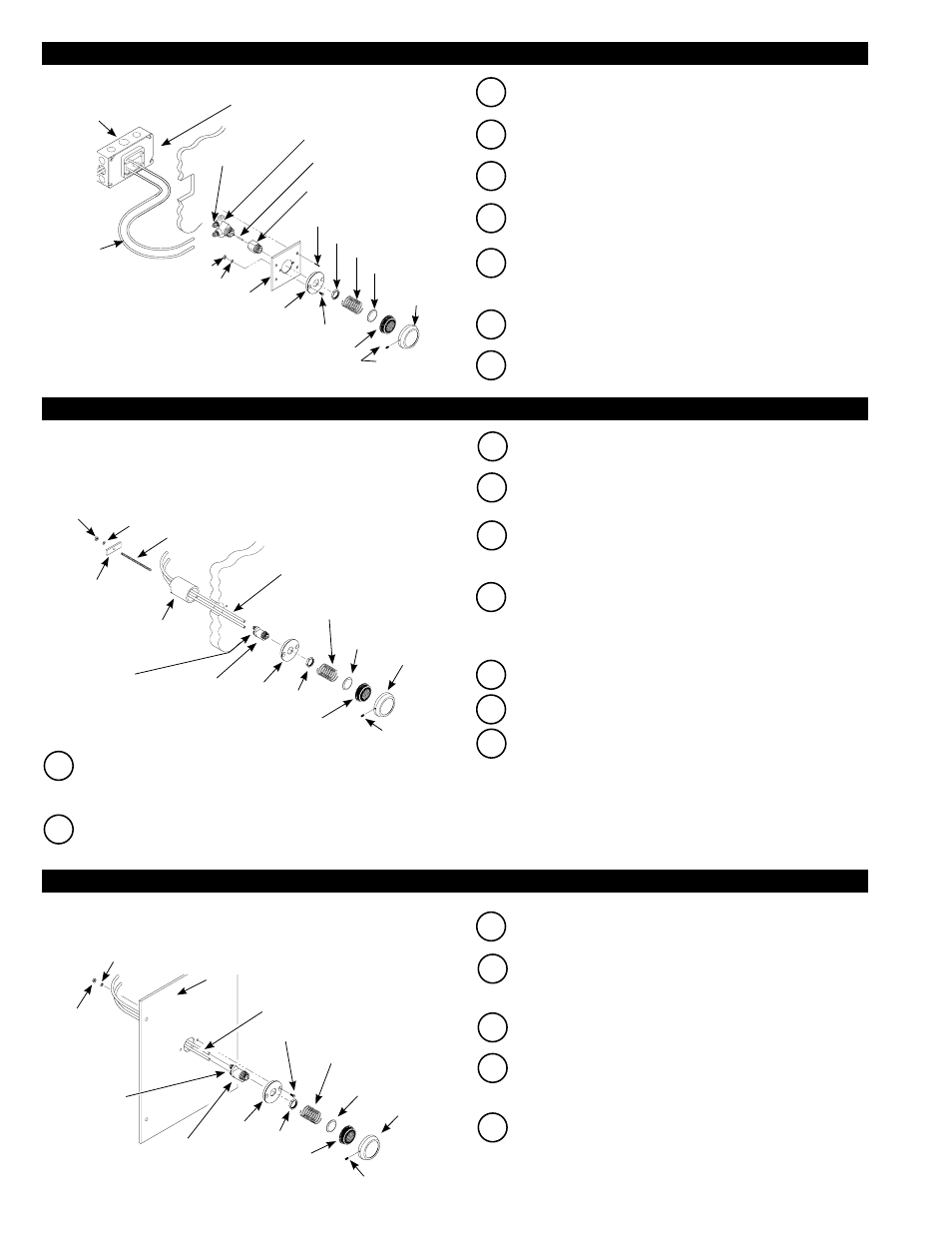
2A - INSTALL HY-72-A SIDE WALL (SW VARIATION) PUSH BUTTON ACTUATOR
2B - INSTALL HY-33-A FIXTURE WALL (FW VARIATION) PUSH BUTTON ACTUATOR
2C - INSTALL HY-33-A FIXTURE WALL (FW VARIATION) WITH WALL BOX PUSH BUTTON ACTUATOR
Note: The HY-33-A Fixture Wall may be installed directly onto fixture wall
where access behind wall is available. If rear access is not available,
HY-33-A may be installed onto a Sloan Easy Access Wall Box Assembly.
Parts for both installations are included with the HY-33-A Push Button.
PUSH BUTTON
SPRING
NUT
WALL
WALL
FLANGE
PUSH BUTTON
ACTUATOR
PLASTIC TUBING
QUICK
CONNECT
FITTINGS (2)
THREADED
ROD
LOCKWASHER
RETAINING
BAR
NUT
BUTTON
FLANGE
SETSCREW
BRASS
INSERT
SPACER SLEEVE —
USE ONLY IF WALL
THICKNESS IS LESS
THAN 2” (51 mm)
Mount Wall Flange onto Cover Plate using (2) Flathead Screws,
Lockwashers and Nuts provided. Tighten Fasteners securely.
A
Insert Extension Stem into Extension Adapter and thread Extension
Adapter onto Push Button Actuator.
B
Insert threaded end of Push Button Actuator Assembly through
Cover Plate Assembly. Fasten to Plate with Nut. Tighten securely.
C
Place Brass Insert into black Push Button. Concave side of Brass
Insert must face outward of Push Button.
D
Insert black Push Button into Button Flange. Place Spring against
Brass Insert of Push Button. Install Push Button Assembly onto
Wall Flange. Secure with Setscrew located on Button Flange.
E
BUTTON
FLANGE
BRASS INSERT
SPRING
NUT
COVER PLATE
SCREWS (4)
EXTENSION
ADAPTER
EXTENSION
STEM
PUSH BUTTON
ACTUATOR
QUICK
CONNECT
FITTINGS (2)
WALL
SET SCREW
PUSH BUTTON
FLATHEAD SCREWS (2)
WALL FLANGE
COVER PLATE
LOCKWASHERS (2)
NUTS (2)
PLASTIC
TUBING
UNIVERSAL
(2) GANG
ELEC. BOX
1-5/8” D x
4-1/2” H x
6-13/16”
W (NOT
SUPPLIED
BY SLOAN)
Mount Cover Plate Assembly onto electrical box cover using the
four (4) Screws provided.
G
Attach Plastic Tubing. See: Steps to Attach Plastic Tubing (Page 5).
F
(2) GANG ELEC. BOX DEVICE COVER 3/4” RAISED
x 4-3/4” H x 7-1/16” W (NOT SUPPLIED BY SLOAN)