1) typical assembly layout – (pts shown) – Space Ray PTS Series Single Stage User Manual
Page 14
Form 43343330
Aug 2012
-13-
7.1)
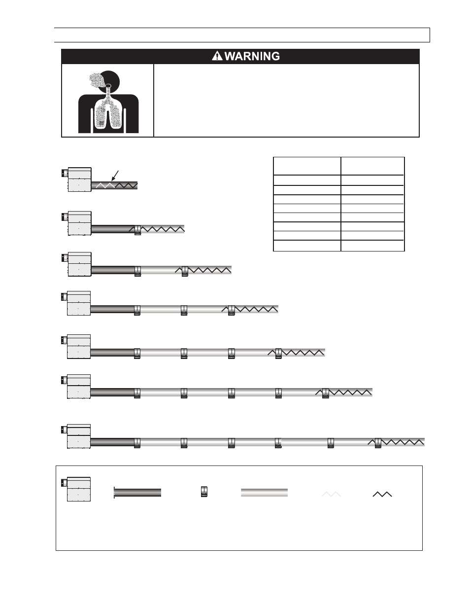
TYPICAL ASSEMBLY LAYOUT – (PTS SHOWN)
Failure to do so may result in death, serious injury, property damage or illness
from Carbon Monoxide poisoning.
The heater must be assembled with the correct number of turbulator sections
and tube length for the rated heat input.
The turbulator must be installed in the last tube section as shown.
POISONOUS GAS AND SOOT HAZARD
60 FT. SYSTEM
50 FT. SYSTEM
20 FT. SYSTEM
30 FT. SYSTEM
40 FT. SYSTEM
LEGEND
Burner Box 10ft Aluminized Tube 24
Hole Flange
or
10ft Alumi-Therm Tube
6 Hole Flange
Coupling
10ft Aluminized or HRS
Tube model dependent
2ft Aluminized
Steel
Turbulator
sections
70 FT. SYSTEM
10 FT. SYSTEM
2ft Stainless
Steel
Turbulator
sections
Stainless Steel Turbulator closest
to burner PTS/U 40 only.
Model
PTS/U 40
PTS/U 50
PTS/U 75
PTS/U 100
PTS/U 125
PTS/U 150
PTS/U 175
PTS/U 200
2 Ft. Turbulator
Sections
4
5
5
3
7
4
0
1