Wire party-line intercom connections – Studio Technologies 45A User Manual
Page 13
Model 45A User Guide
Issue 2, November 2011
Studio Technologies, Inc.
Page 13
unbalanced source in this manner results
in hum or noise, connect XLR pin 2 to high
(+ or hot) and pin 3 to shield; leave pin 1
unterminated.
4-Wire Line Outputs
The Model 45A’s dual-channel interface
provides two analog line-level audio out-
puts. These outputs are intended to be
connected to inputs on the devices asso-
ciated with the 4-wire audio signals. The
outputs are capacitor coupled, transform-
er balanced with a nominal level of +4
dBu. The 4-wire line outputs are capable
of driving inputs that have impedances as
low as 600 ohms, however connecting to
loads of 2 k ohms or greater is preferred.
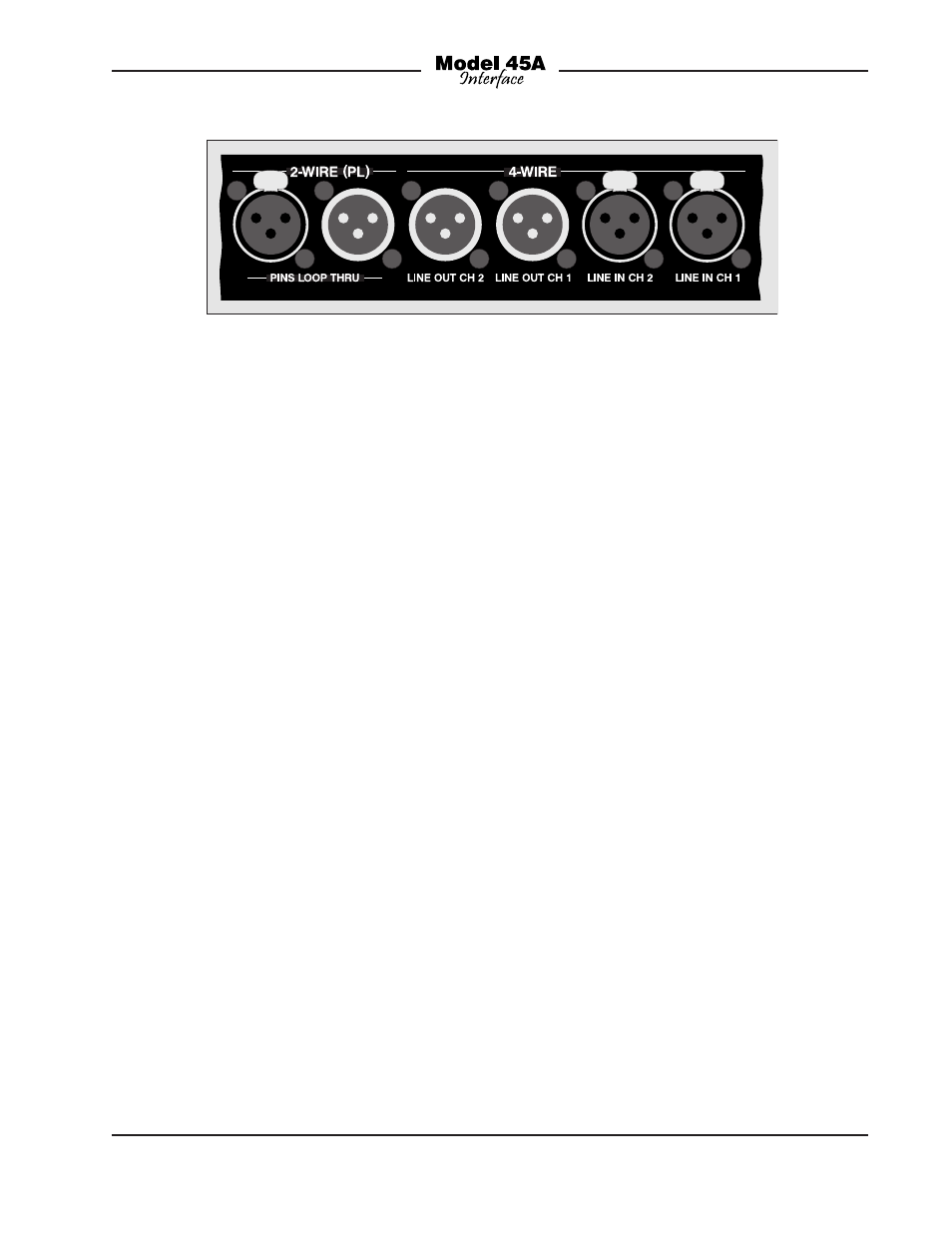
The line outputs are connected by way of
3-pin male XLR-type connectors which are
located on the Model 45A’s back panel.
Refer to Figure 4 for a detailed view.
The mating connectors (females) should
be prepared so that signal high (+ or hot)
is expected on XLR pin 2. Signal low (– or
cold) should be expected on XLR pin 3.
The cables’ shields can be connected
to XLR pin 1. However, in order to mini-
mize the chance that ground-interaction
problems will arise, pin 1 on each of the
line output connectors is isolated from all
Model 45A circuitry and ground points.
“Floating” pin 1 virtually eliminates the
chance that a “ground loop” problem will
occur.
2-Wire Party-Line Intercom
Connections
The Model 45A’s 2-wire party-line intercom
interface is designed to connect with a
standard single- and dual-channel party-
line intercom circuit. This type of circuit
typically has positive 28 to 32 volts DC
on pin 2 and common on pin 1. The Model
45A’s 2-wire party-line interface can also
serve as an intercom power source and
200 ohm impedance generator, allowing
intercom user devices to be directly con-
nected. The Model 45A’s internal 30 volt
DC intercom power source is limited to
300 milliamperes of current. This moder-
ate amount of power requires that the type
and number of connected user devices
be selected appropriately.
For convenience, the 2-wire party-line
intercom circuit or user devices can be
connected to the back of the Model 45A
by way of either a male or female 3-pin
XLR-type connector. For flexibility during
use, an additional male 3-pin XLR-type
connector is located on the front panel.
The three connectors are wired in paral-
lel (“multed”) and provide access to the
identical signals.
Figure 4. Detail of back panel showing line inputs and outputs