Sfp module flexibility – Studio Technologies 5150 V.1 User Manual
Page 27
Model 5150 User Guide
Issue 5, March 2014
Studio Technologies, Inc.
Page 27
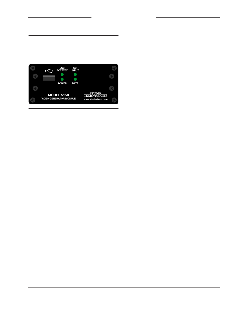
Model 5150
Video Generator Module
2. After a slight pause one of the four LEDs
will light briefly. This will indicate the
major number of the MCU’s firmware
version. The LED will stop lighting then
another one of the four LED will light
briefly to indicate the minor number of
the MCU’s firmware version. The range
of each is 1-4. A period (.) is inserted
between the major and minor numbers.
As an example, if the USB Activity LED
lights first followed by the SDI Input LED
lighting this would indicate version 1.2 of
the MCU firmware.
3. After another slight pause one of the
LEDs will light briefly. This will indicate
the major number of the FPGA’s firm-
ware version. The LED will stop lighting
then another one of the four LED will
light briefly to indicate the minor num-
ber of the FPGA’s firmware version.
The range of each is 1-4. A period (.) is
inserted between the major and minor
numbers.
As an example, if the SDI Input LED
lights twice this would indicate version
2.2 of the FPGA firmware.
4. After a final short pause the four LEDs
will begin performing in their normal
operating manner. The Power LED will
light and remain lit. The USB Activity
LED will only be active when a USB
flash drive is inserted and file transfer
activity is taking place. The SDI Input
LED will light whenever a valid SDI
signal is connected to either the coaxial
(BNC) input or the optical input, de-
pending on the module’s capability and
configuration setting. The Data LED will
light whenever local data is received
via the RS-485 data bus from a Studio
Technologies’ Model 5190 Remote
Access Module.
SFP Module Flexibility
The Model 5150 was designed to allow an
MSA-compliant SFP optical module to be
installed at the factory. Optical modules are
available with a range of input and output
capabilities to meet the needs of various
applications. For maximum flexibility the
SFP mating connector and associated
“cage” on the Model 5150’s FPGA circuit
board were implemented to meet the elec-
trical and mechanical requirements of the
MSA SFP standard. The MSA SFP stan-
dard was originally developed for use with
optical data (Ethernet) modules. It has
also become popular for use with SFP
modules that support SMPTE-compliant
SDI signals.
It’s interesting to note that several compa-
nies offer non-optical SFP modules that
support the MSA SFP standard as well.
For example, Embrionix of Canada offers
a wide range of specialized SFP modules.
These include coaxial SDI input and output
modules that use DIN 1.0/2.3 and HD-BNC
connectors. In addition, they offer SFP
modules that provide an HDMI® output.
The USB Activity LED lights to represent the number 1
The SDI Input LED lights to represent the number 2
The Power LED lights to represent the number 3
The Data LED lights to represent the number 4
Figure 9. Detail of front panel showing how
the LEDs display the MCU and FPGA firmware
version numbers.