Studio Technologies 47 User Manual
Page 14
Issue 1, August 2010
Model 47 User Guide
Page 14
Studio Technologies, Inc.
intercom channels whenever the func-
tion is activated. Independent control of
sending “mic kill” signals to interface 1 or
interface 2 is not supported. User intercom
devices compatible with this 24 kHz “mic
kill” signal include RTS TW-series belt
packs such as the BP325.
The opto-coupled remote control inputs
are designed for direct connection with
3.3 and 5 volt DC logic signals. An internal
475 ohm resistor, in series with each opto-
coupler’s photodiode, acts to limit the
current flow. Signals of up to 32 volts DC
can be safely connected as long as the
current is limited to 20 milliamperes maxi-
mum. If necessary, an external resistor
can serve to limit the current. For example,
with a 12 volt DC signal using a 560 ohm,
¼-watt resistor in series with the connec-
tion would be appropriate. With a 24 volt
DC control signal a series resistor of 1.8 k
(1800) ohms is recommended. No matter
the source voltage, for correct operation
a minimum current of 2 milliamperes is
recommended.
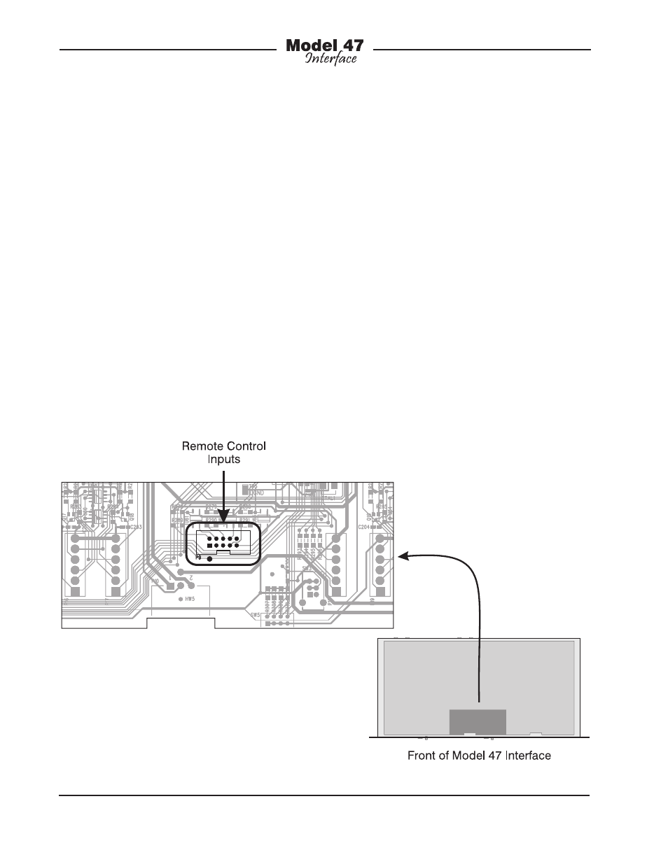
Access to the remote control inputs is pro-
vided by means of a 10-pin male “header”
connector which is located on the Model
47’s circuit board. Refer to Figure 3 for
a view of the connector’s location. The
“keyed” and “shrouded” header follows a
common industry-standard specification:
two rows of five pins each with 0.1 inch
between rows and pins. The mating con-
nector is intended to be an insulation-
displacement (IDC) socket connector such
as the Tyco 1658620-1. The connector
would be “crimp” terminated onto a piece
of 10-conductor flat ribbon cable. This
ribbon cable can safely exit the Model 47
Figure 3. Location of 10-Pin male header connector on the Model 47 printed circuit board