Studio Technologies 60 User Manual
Page 9
Issue 2, March 1998
Model 60/61 User Guide
Page 12
Studio Technologies, Inc.
sources or having to buy a separate audio
routing switcher. Our final decision was
easy once we realized that by including an
insert switcher the features of a 4 input/1
output stereo source switcher would also
be provided! Follow the next paragraph if
you want to implement a source switcher
instead of an insert switcher.
output) and a return (an input); tip is send,
ring is return, and sleeve is shield. So for
each stereo device you’ll need two insert
cables, each having both a send and a
return plug.
While you can certainly prepare your own
“Y-cables,” it is far easier to use pre-made
insert cables. Your dealer or distributor
can assist you in getting the exact cables
you need. Studio Technologies has all its
production test cables custom made by
RAPCO International, Inc. (Jackson,
Missouri 63755, U.S.A., (800) 467-2726)
with great results. They follow our excruci-
atingly detailed specifications without a
complaint!
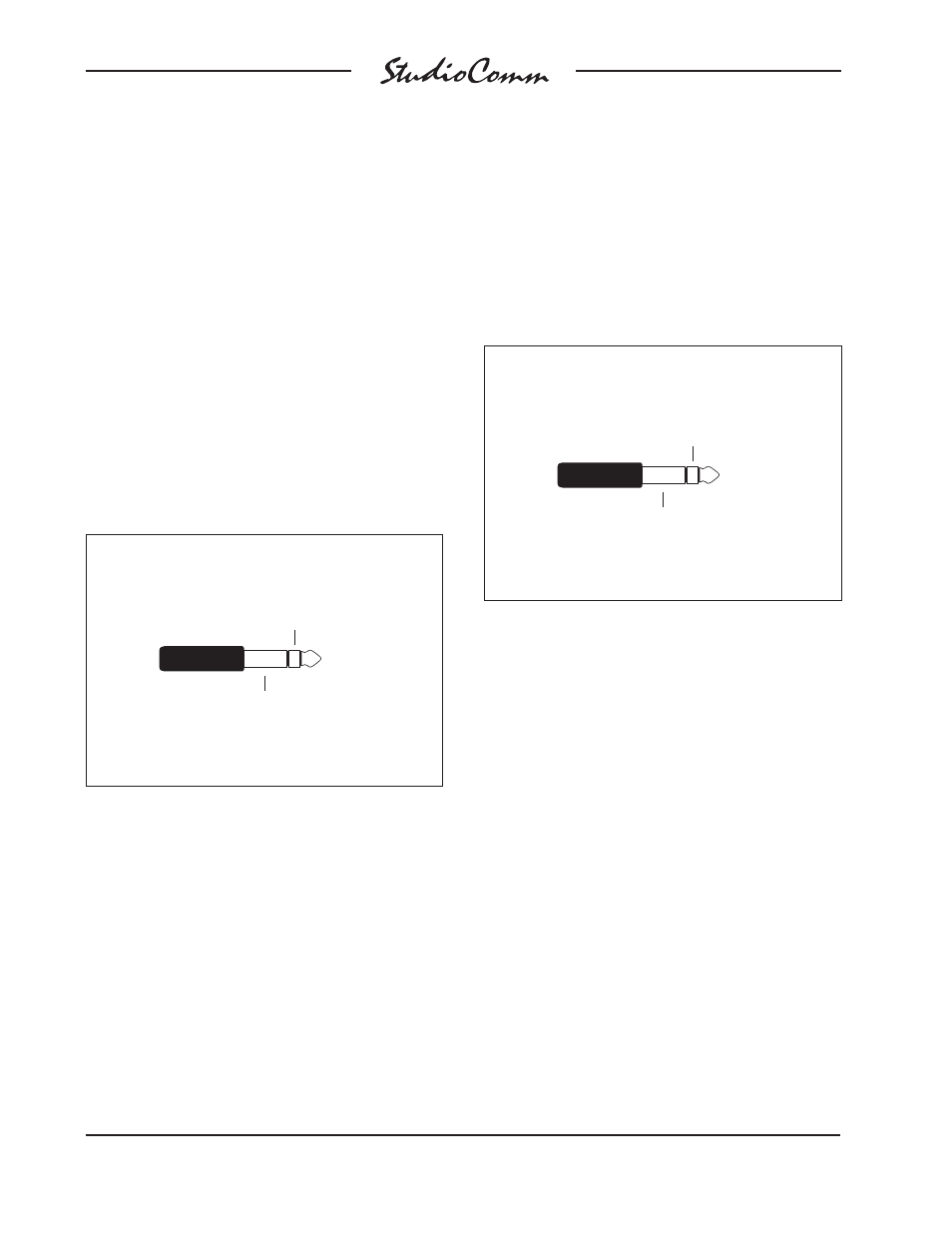
Insert Switcher Insert Connections
(Switchcraft No. 297, Neutrik NP3C or equivalent)
Sleeve: Shield
Ring: Return (Input)
Tip: Send
(Output)
Using the Insert Switcher as an Input
Source Switcher
Frankly, when we were designing the
Model 60 the decision to include an insert
switcher versus including an input source
switcher was difficult. While an insert
switcher had a lot of merit, it would also be
useful to include a feature that would allow
analog sources such as CD players,
cassette decks, or microphone preamplifi-
ers to be easily selected as an analog
input to a workstation. This would save
time by eliminating the need to patch
Insert Switcher Insert Connections
when used as Audio Input
Tip: No
Connection
(Switchcraft No. 297, Neutrik NP3C or equivalent)
Sleeve: Shield
Ring: Input ( + )
The first audio source should be con-
nected to the insert input jacks. Using
¼-inch plugs, connect tip to audio high (+
or hot) and sleeve to shield. Sources 2, 3
and 4 will be connected to the three insert
jacks (labeled A, B, and C) by means of a
non-standard wiring scheme. Using ¼-inch
plugs, connect ring to audio high (+ or hot)
and sleeve to shield; don’t connect any-
thing to the tip lead. To be even more
clear: you must use a 3-conductor plug
and leave the tip floating (isolated)—be
warned! The insert output jacks serve as
the output of the source switcher. Using
¼-inch plugs, connect tip as audio high
(+ or hot) and sleeve as shield.
Stereo Line Inputs
The Model 60 provides four stereo line-
level inputs. Each input is electronically
balanced and can be individually config-
ured for compatibility with +4dBu or