Wiring diagram – network connection, Below is a wiring diagram for a network connection – Super Systems Paperless VR User Manual
Page 10
Advertising
Super Systems Inc.
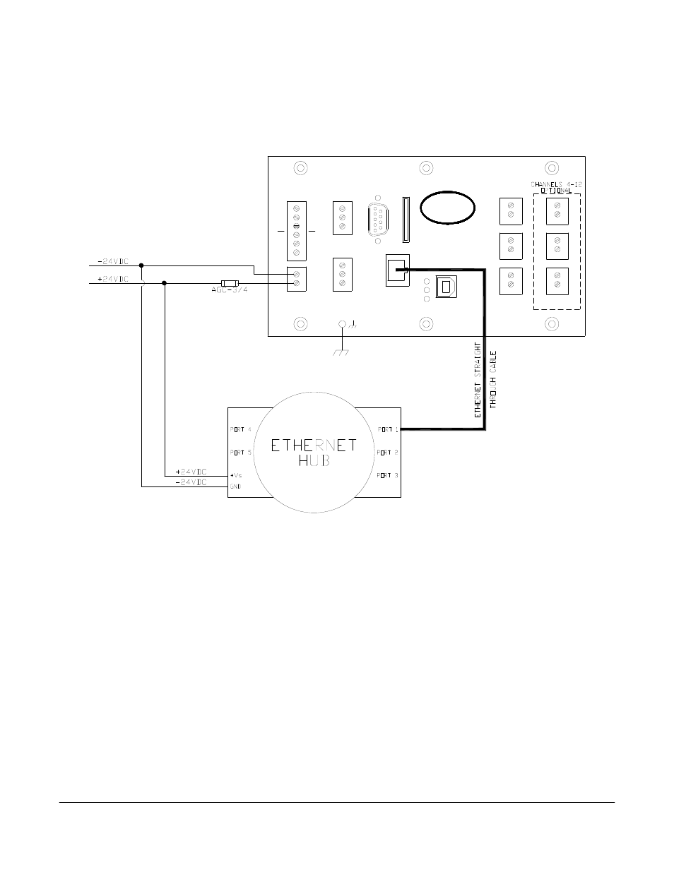
Page 9 Video Recorder Manual Version 2 Rev. B
Wiring Diagram – Network Connection
Below is a wiring diagram for a network connection:
-
DC
24V
HOST
REMOTE
USB
ETHERNET
RS485
+
-
+
S
+
S
-
2
1
1
+
-
4
+
-
+
2
-
+
5
-
RS485
HOST/SLAVE
SLAVE
S
+
-
Tx
Rx
G
SLAVE
RS232
HOST
RS232
SSi
CINCINNATI, OHIO
+
3
-
+
6
-
Advertising
See also other documents in the category Super Systems Equipment:
- Bazooka Probe (10 pages)
- Gold Probe (16 pages)
- HP2000 With 9100 Controller (10 pages)
- HP15 (23 pages)
- SuperOX (14 pages)
- PGA3000 (16 pages)
- PGA3500 (26 pages)
- e-TRIM (27 pages)
- 9120 with TS (80 pages)
- MGA6000 (42 pages)
- DP2000 (17 pages)
- DPC3500 (5 pages)
- MGA6010 (54 pages)
- DPC2530 (17 pages)
- Simple Dew (18 pages)
- DPL4000 (16 pages)
- H2 Sensor (17 pages)
- Hydrogen Nitrider Analyzer (12 pages)
- PH2 (19 pages)
- AC20 Quick Start (5 pages)
- XGA Viewer (46 pages)
- AC20 RS485 Modbus (62 pages)
- AC20 (114 pages)
- 20Q Calibration Manual (9 pages)
- CAT-100 (51 pages)
- 7EK 31080 (32 pages)
- 7EK 31082 Calibration Manual (5 pages)
- 7EK 31081 (36 pages)
- 7EK 31082 (34 pages)
- 20PQ (170 pages)
- X5 Calibration Manual (1 page)
- 20Q (126 pages)
- 7SL (36 pages)
- X5 (74 pages)
- 9000 Series (15 pages)
- 3L Series (54 pages)
- 9015 Series (11 pages)
- 3 Series (92 pages)
- 9010 Series (66 pages)
- 9210 Series (65 pages)
- 9130 Series (174 pages)
- PC Configurator 2 Quick Start (15 pages)
- 9100 RPS (10 pages)
- 9125 Series (235 pages)
- 9120 RPS (11 pages)