Tecfluid 2000 Series User Manual
Page 2
Technical characteristics
•
Precision according to VDE/VDI 3513:
- 2100
± 4% f. s. value
Class 4
- 2150
± 2,5% f. s. value Class 2,5
- 2300/2340
± 1,6% f. s. value Class 1,6
•
Standard Scales:
- Water in l/h.
- Air in Nl/h up to 700 Nl/h.
- Air in Nm³/h from 1 to 17 Nm³/h.
(on demand in l/s, cc/min, %.)
•
Mounting:
Vertical (rising fluid).
•
Fittings:
- 2100/2150/2300
Rp 1/4” (BSP) or 1/4” NPT
- 2340
Rp 1/2”, Rp 3/4” (BSP) or
1/2”, 3/4” NPT
•
Materials:
- Metering tube: Borosilicate Glass
- Fittings:
EN 1.4404 (AISI-316L)
- Float: EN 1.4404 (AISI-316L),
Aluminium, Glass, Ceramic
PVC, PVDF, PTFE.
- Valve:
EN 1.4404 (AISI-316L)
- Valve seat:
PTFE
- Gaskets:
NBR (Nitrile Rubber)
( Viton
®
on demand)
•
Working Pressure:
15 bar max.
•
Fluid temperature:
0 ... +120ºC.
•
Ambient temperature: 0 ... +80ºC.
Conforms with Directive 97/23/CE
•
Optional limit switches:
- 20-AMD
Bi-stable inductive proximity detector, NAMUR
DIN 19234
Conforms with Directive EMC 89/336/EEC
- 20-AMO
Optical limit switch (for clear fluids).
• Power supply:
12 VDC, 24 VDC, 24 VAC,
110 VAC, 230 VAC, 240 VAC.
Conforms with Directive EMC 89/336/EEC
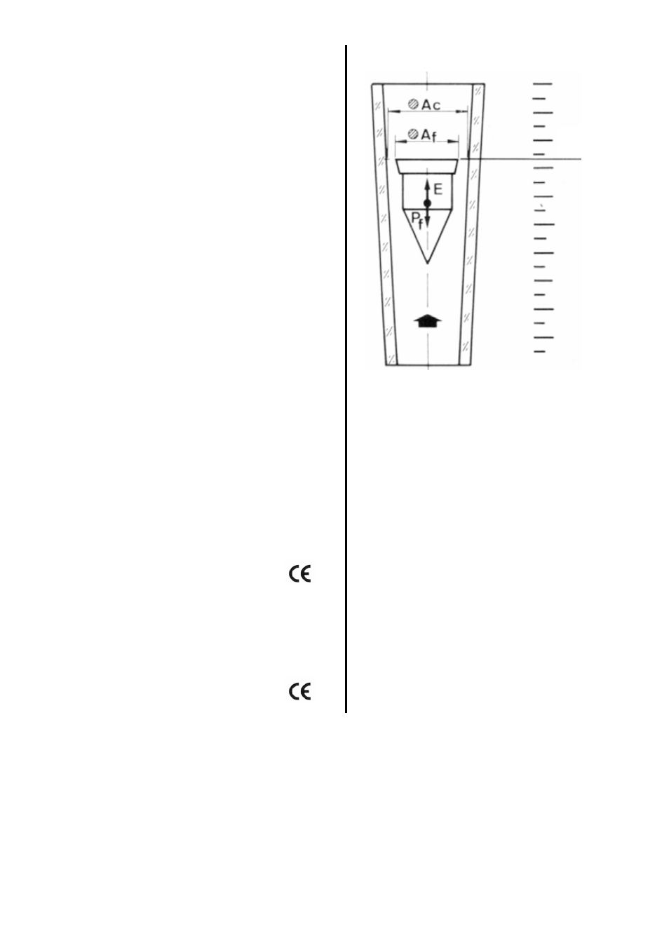
Working Principle
The flowmeter consists of a float inside a conical
tube.
The rising flow pushes the float to an equilibrium
point. The area obtained between the float and
the tube is proportional to the flow rate.
This type of measuring principle is known as
variable area.
The equilibrium point depends on :
− The float weight
:
Pf
− The fluid thrust :
E
− The free flow area : Al
The area proportional to the flow rate will be:
Al = Ac - Af
where:
Ac = Flow metering tube area
Af = Float area
Each position of the float corresponds to a flow
rate indicated on the scale printed on metering
tube.
Reading
Line
RECEPTIÓN
The flowmeter is supplied ready for use.
Turning the apparatus carefully upside down, check that the float moves freely.
MOUNTING
The flowmeter must be mounted vertically taking into account that:
The fluid inlet is at the bottom (the low end of the scale).
The fluid outlet is at the top (the high end of the scale).
It is most important that the flowmeter is installed perfectly vertical, given that deviations of the
order of 5-10º from the vertical can produce reading errors of up to 10%.
2