Tecfluid LD61N User Manual
Page 3
Once the connector is opened, pass the cables through the cable gland and screw in the
cables in their positions, depending on the desired working mode, as explained below.
The working mode (maximum or minimum detection) is given depending on how the
cables are connected (see next page).
3
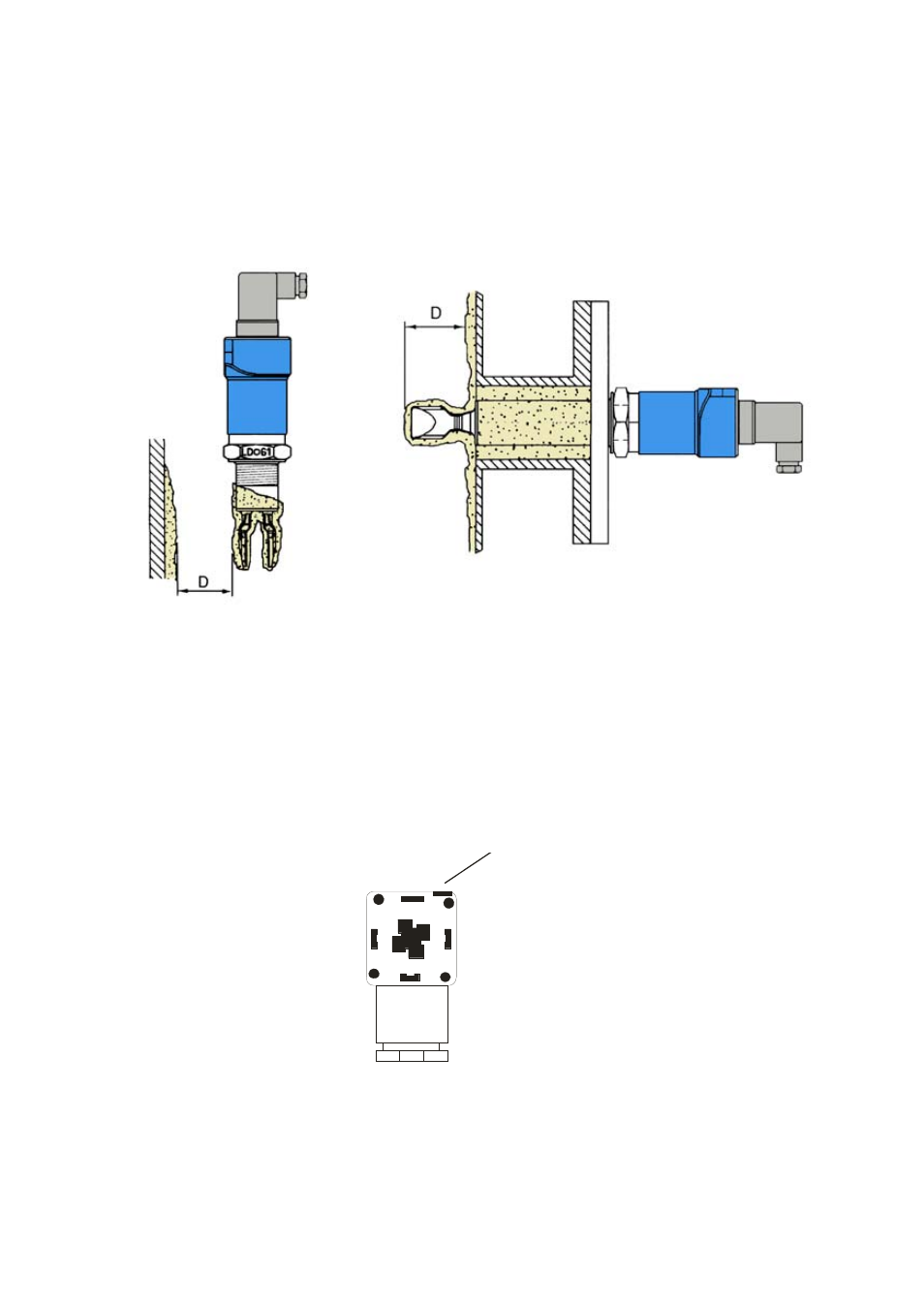
In the same way, when the detector is installed where there is flow, the position must be
taken into account. The flat part of the tines must be aligned parallel with the flow direction
as shown in figure 1.
If the viscosity is high, the tines must be kept away from other objects (such as the wall of
the tank). In these cases it is preferable to install a longer detector (figure 2).
The cable gland should be situated on the lower side of the connector. If it is necessary,
the position of the connector can be changed by 90º or 180º. To do this, open the
connector and rotate. This operation must be done with the power disconnected.
Ranura de apertura
4. ELECTRICAL
CONNECTION
The LD61N can be installed as a detector of minimum or maximum level. The electrical
connection is made by means of a DIN 43650-A connector with a PG9 cable gland.
Multiple conductor cable with sections about 0,5 mm
2
should be used.
To open the connector, remove the centre screw and prise open using a small
screwdriver in the slot shown in the following drawing (looking at the female connector
from the contact side).
Figure 2
Slot to open the connector