Tecfluid MT-02 User Manual
Page 4
4
Cod.:E-MI-2151001I Rev.: 2
2
SETTING UP AND PROGRAMMING
2.1
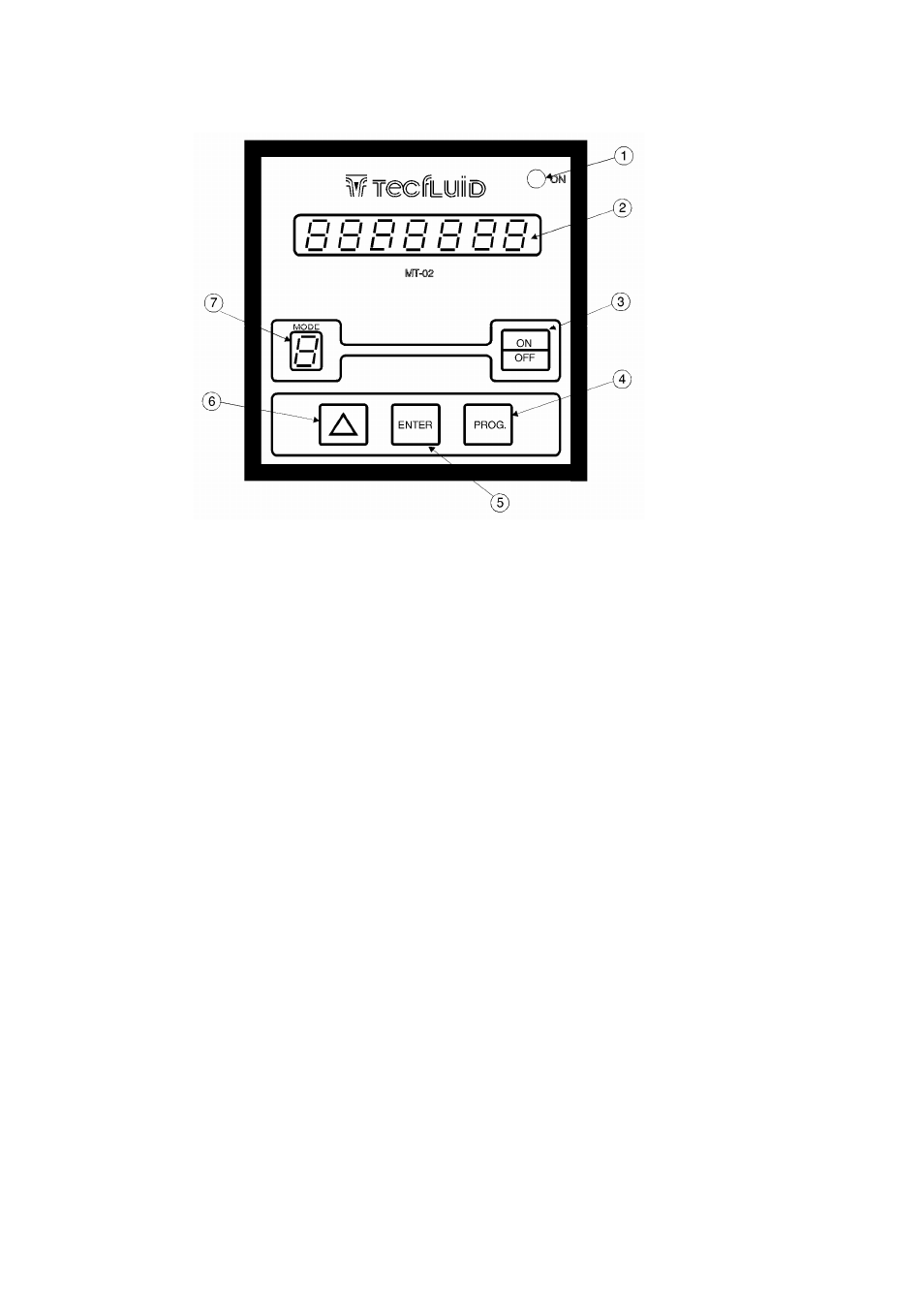
Description of the front panel
1.
Red LED power supply pilot light .
2.
7 Digit LED Display
3. "ON/OFF"
Push-button
4. "PROG."
Push-button
5. "ENTER"
Push-button
6.
Increment Data "
∆" Push-button
7.
Working MODE Indicator
0
=
Standby
1
=
Batching
2
=
Total
Volume
Indication
L
=
Litres/pulse
programming
P
=
Preset
programming
The MT-02 has four Push-buttons to control the different working modes as explained in these
instructions. The 7 segment Light Emitting Diode (LED) Display is used to visualize the working data.
The "MODE" Indicator [7] is used to indicate in which of the different working modes the program is
situated. The LED pilot light is only for indicating the presence of mains supply voltage; in the event that
the mains fuse blows, the pilot light will be off.
2.2
Starting
up
When the mains supply is connected, at first the equipment makes an auto-check of the display
and then checks the memory (RAM) and the state of programming. In the event that the MT-02 has not