Tecfluid CI-420 User Manual
Page 5
5
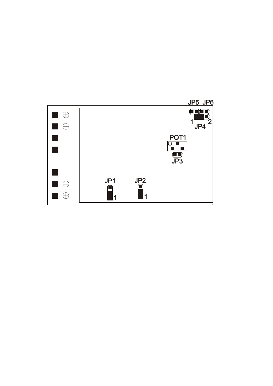
In the examples given, the jumper is shown as a black filling.
In the four examples we can see how to program the frequency which corresponds to the maximum
output.
When changing the maximum frequency, this should be done with the instrument disconnected from
the mains supply. The instrument reads the switch data only when it is switched on.
4. CONFIGURATION
It is not normally necessary for the user to have to change the basic configuration of the instrument,
given that the CI-420 is supplied according to the clients specifications.
In the example given the instrument is configured for a COVOL input and 4-20 mA output.
The JP1 and JP2 jumpers are used to configure the type of input and should not be moved
The jumpers JP3, JP4, JP5 & JP6 are used to configure the type of output.
Beginning Full JP3 JP4 JP5 JP6
of Scale Scale 1 2
1. 0 mA 20 mA X X
2. 4 mA 20 mA X
3. 0 V 5 V X X X X
4. 0 V 10 V X X X
5. 1 V 5 V X X X
6.
2 V 10 V X X
Jumpers JP5 and JP6 are used only for voltage outputs, and have only one position.
Jumper JP3 fixes the full scale range.
Jumper JP4 is used to determine the beginning of the scale and has two positions, "1" towards the
top of the PCB and "2" towards the bottom of the PCB.
The jumpers should be placed in the position marked with "X".
The potentiometer POT1 can be used for fine adjustment of the full scale reading.