4/ connecting the device, 5/ lock the device on the hook-on bracket, S1 s2 – Thermor Emotion User Manual
Page 15
13
4/ Connecting the device
- The device must be supplied with 230V, 50Hz.
- Mains connection must be ensured using the 3-
wire cable factory fitte to the heater , through
a connecting box. In damp premises, such as
bathrooms and kitchens, install the connecting
box at least 25cm from the ground.
- To prevent hazards due to unintentional reset-
ting of the thermal circuit breaker, this device
should not be powered through an external
switch, such as a time switch, or connected to
a circuit which is switched on and off on a
regular basis by the electric power supplier.
- The installation must comply with local natio-
nal regulation. If in doubt, ask the national Atlantic distributor.
- Ground connection is forbidden. Do not connect the pilot wire (black) to ground.
- If power cable is damaged or too short, to avoid any danger it must be replaced by a qualified electri-
cian using special tools.
- If a heater pilots or is piloted by a 30mA differential (e.g. bathroom), the pilot wire supply must be pro-
tected on this differential.
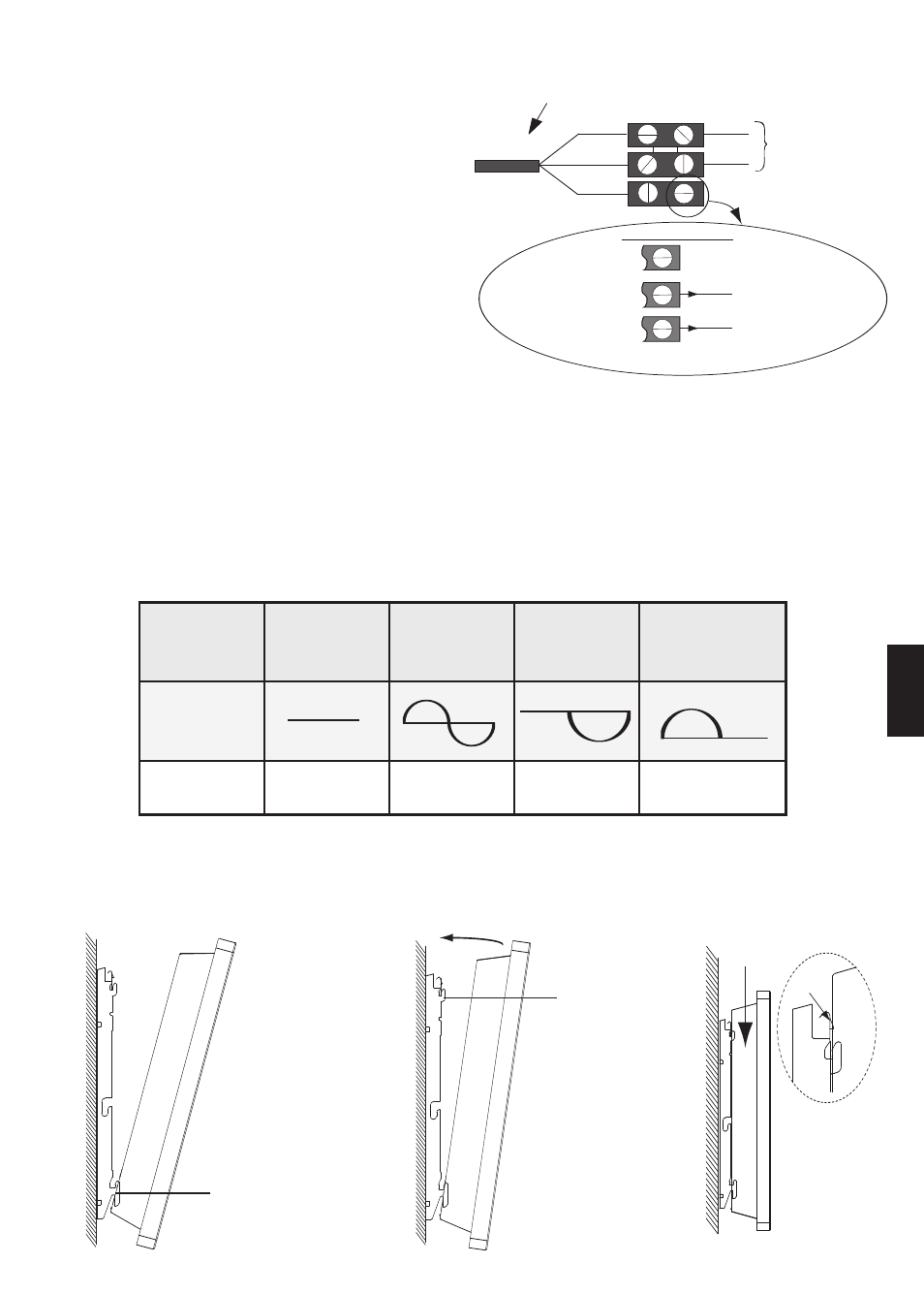
Panel heater cable
Phase=brown
Neutral=blue
PHASE
NEUTRAL
Electricity
grid
Three possible cases
Pilot wire=Black
1st case: only one heater
2nd case: Slave heater
3rd case: Master heater
The pilot wire end is insulated
and not further connected
To the appliance with cassette or
programming unit.
To pilot wire of an electronically
controlled appliance
Chart indicating the orders the device can receive over its pilot wire
(to be measured between the pilot wire and the neutral).
Orders received Current absent
Full wave 230V
Negative half
wave -115V
Positive half wave
+115V
Ref/neutral
oscilloscope
Mode achieved
COMFORT
ECO
STANDBY
STOP HEATING
LOAD SHEDDING
5/ Lock the device on the hook-on bracket
S1
S2
CLICK
GB