Tri Tool 601SBM Clamshell Air User Manual
Page 24
24
TRI TOOL INC.
92-0092 Rev. 131230
CONFIGURE THE CLAMSHELL FOR THE SPECIFIC TASK REQUIRED
Select the proper Tool Blocks.
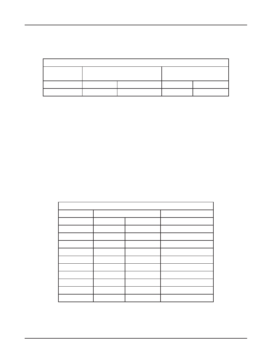
Tool Block Selection
Tool Block
Assy
Height from Centerline of the
cut to the Headstock Face
Tool Block Travel
08-0036
1.50"
38.1 mm
.63"
16.0 mm
08-0096
.51"
13.0 mm
.50"
12.7 mm
Mount the Tool Blocks and Tripper Block to the Clamshell.
Check the adjustment of the slides and mesh of the Tripper Pin with the Feed
Sprocket.
Select the proper Clamping Pad Set. Refer to the table ‘Pad Set Selection’.
Install the Clamping Pad Set into the clamshell.
If using the Fixed Clamping Pad Set then install the Clamping Pad Set so that the
pipe is on the fixed Pads or vice versa.
Fixed Pads should be located 90
o
from each other.
Pad Set Selection
Pipe Size
OD
P/N of Pad Sets
1.00"
1.315"
33.4 mm
67-3156
1.250"
31.8 mm
67-3157
1.125"
28.6 mm
67-3158
.75"
1.050"
26.7 mm
67-3159
1.000"
25.4 mm
67-3160
.875"
22.2 mm
67-3161
.50"
.840"
21.3 mm
67-3162
.750"
19.1 mm
67-3163
.38"
.675"
17.1 mm
67-3164
.625"
15.9 mm
67-3165
.25"
.540"
13.7 mm
67-3166