18 fitting an extension pumphead – Watson-Marlow 701 User Manual
Page 17
Position the left-hand end of the track so that the track-securing bolt can be inserted.
Tighten the track-securing bolt with the 6mm Allen key provided.
Tighten both the track-compression spring knobs to a torque of 3Nm (2.2 lb-ft) using a
10mm A/F spanner.
Connect both ends of the tubing element to the fluid line using 3/4in female cam and
groove connectors.
18 Fitting an extension
pumphead
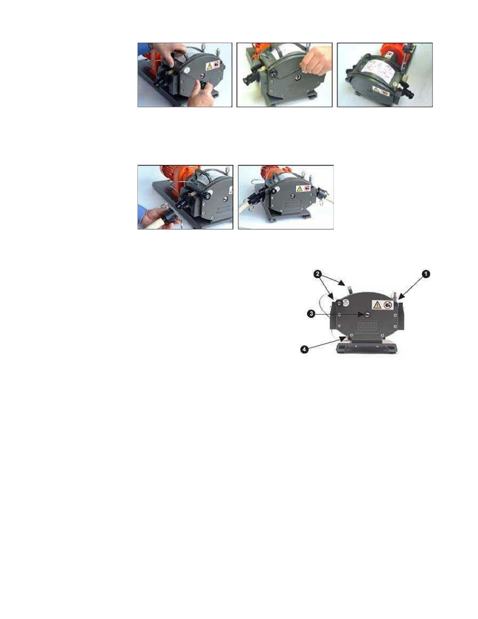
From the first pumphead remove:
the plug from the tapped hole in the top right
hand corner of the pumphead frontplate (1);
the track securing bolt and the track (2);
the plug from the slot in the centre shaft (3);
the M8 x 16 socket head cap screw from the
bottom left of the first pumphead (4).
Grease the drive shaft dog of the extension pumphead with the grease supplied.
Apply thread locking compound to the M8 x 16 socket head cap screw in the top right
hand corner of the backplate of the extension pumphead.
Align the drive shaft dog of the extension pumphead with the slot in the drive shaft of
the first pumphead.
Fit the extension pumphead to the first pumphead. Ensure the backplate of the extension
pumphead is flat against the frontplate of the first pumphead.
Lightly tighten the socket head cap screw with the modified 6mm Allen key provided.
Apply thread locking compound to the M8 x 170 socket head cap screw in the bottom left
of the extension pumphead frontplate, and tighten it in sequence with the M8 cap screw
in the backplate.
Page 17 of 25
Watson-Marlow Bredel E-Manuals
14/12/2009
file://M:\staging\pdfs-global\m-701baseplate-gb-02.htm