Watson-Marlow 504S User Manual
Page 3
3
particularly for materials of a viscous nature. Silicone and Marprene tubing is available with 2.4mm wall thickness for speeds up
to 200rpm.
DO keep the track and rollers clean.
DO fit an extra length of pump tube in the system to enable tube transfer. This will extend tube life and minimise the down time
of the pumping circuit.
The self-priming nature of peristaltic pumps means valves are not required. Any valves fitted must cause no restriction to flow in
the pumping circuit.
When using Marprene or Bioprene tubing, after the first 30 minutes of running, re-tension the tube in the pumphead by
releasing the tube clamp on the delivery side a little and pulling the tube tight. This is to counteract the normal stretching that
occurs with Marprene and Bioprene, which can go unnoticed and result in reduced tube life.
Tube selection The chemical compatibility list published in the Watson-Marlow catalogue is only a guide. If in doubt about the
compatibility of a tube material and the duty fluid, request a tube sample card for immersion trials.
Installation
The 504S/RL is suitable for single phase mains electricity supplies only.
To ensure correct lubrication of the gearbox the pump should be run only while its feet are standing on a horizontal surface. The
pump should be positioned to allow a free flow of air around it.
•
Remove the small transparent plate on the rear panel to gain access to the voltage selector and terminal block.
•
Set the voltage selector switch to either 120V for 100-120V 50/60Hz single phase AC supplies or 240V for 220-240V 50/60Hz
single phase AC supplies.
•
Route the mains supply cable through the entry point to the right of the recess and couple the cable to the terminal block as
shown on the rear panel.
•
The cable entry accepts three core 0.75 square millimetre PVC sheathed mains cable (via the screw adaptor supplied) so
that a mains lead can be used.
•
Ensure that the mains lead is securely retained in the strain relief gland so that IP55 ingress protection is maintained.
•
Securely replace the transparent plate and the gasket over the recess.
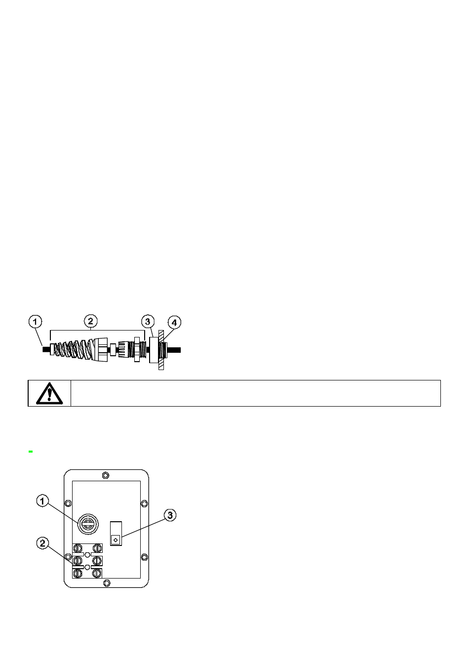
1 Power cable 5-8mm O.D. (outside diameter)
2 Strain relief gland SL 0020
3 Adaptor MR0678T
4 M20 Conduit thread for direct conduit connection, through back panel
Ingress protection standard will be compromised if fittings are not correctly replaced.
Rear panel recess
The pump rear panel recess houses the following:
1 Fuse holder 2 Terminal block 3 Voltage selection switch
Troubleshooting
Should the unit fail to operate, make the following checks to determine whether or not servicing is required.