Watson-Marlow MasoSine Ecosine Assembly User Manual
Assembly/disassembly instruction sheet, Wet end disassembly
1. Loosen and remove the wing nuts, item 441, and slide the front
cover, item 400, off the studs, item 450. If necessary, a rubber
mallet may be used to separate the cover from the pump
housing by tapping on the front cover pins, item 420.
2. Remove the scrapergate support, item 370, from the front
cover. If the scrapergate support is stainless steel, remove the
dynamic face o-ring, item 515, from the groove.
3. The front cover o-ring, item 430, may now be removed from
the groove in the pump housing face.
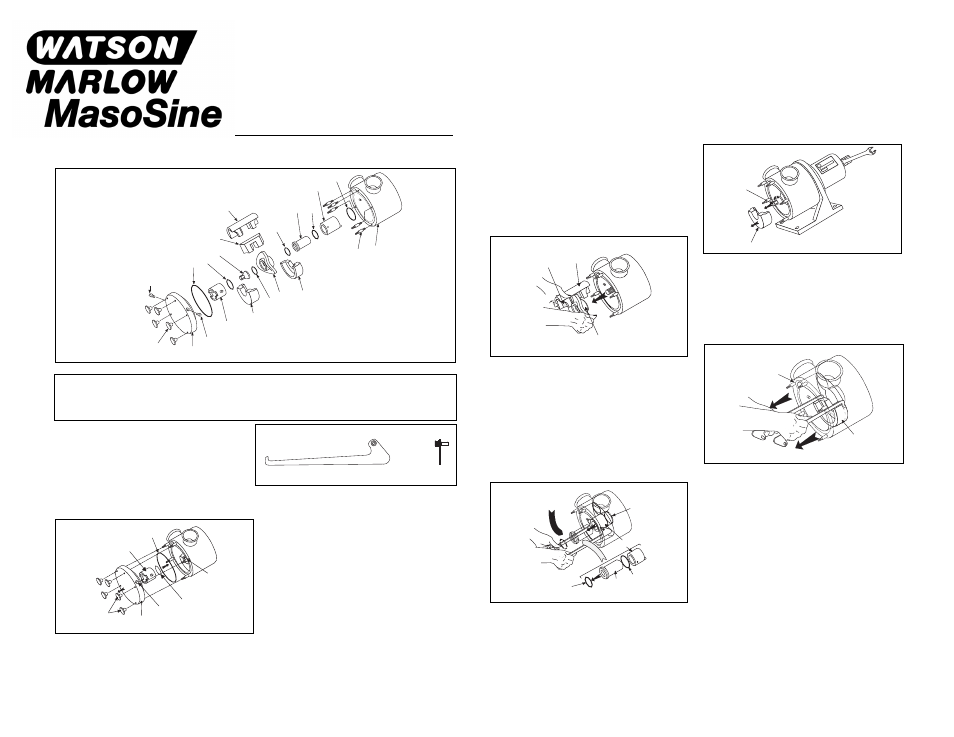
Assembly/Disassembly Instruction Sheet
NOTE
Reference the isometric drawing for parts
identification while following the wet end
disassembly and assembly steps.
7. Remove the rear liner, item 072. This is where the liner/seal
housing removal tools will be helpful. Insert the hooked ends of
the liner pullers into the slots located on each end of the liner.
Again, apply even pressure on both ends to prevent the liner
from lodging in the pump housing.
6. Next, the rotor, item 011, the scrapergate, item 125, and the
scrapergate guide, item 100, can be pulled off the shaft and
removed from the pump housing. This will require two hands.
4. Remove the front liner, item 072, by pulling with even pressure
on both ends.
5. Remove the shaft nut, item 231. Wrench flats have been
machined into the rear of the shaft to secure the shaft while
loosening the nut. The rotor o-ring, item 030, can now be
removed from the groove in the shaft nut.
WARNING:
Before attempting assembly/disassembly of the Sine Pump, be sure that the power source to the drive is disconnected or
locked out. Ensure that the electrical switch gear cannot be operated while work is performed on the pump. Failure to do so
could result in severe personal injury from rotating components.
TOOLS
Removal tools are supplied with every new Sine Pump. The
tools are shaped like skate blades and have a pin extending
from one end. These tools are used for removing the rear liner
and seal housing.
Steps: 1, 2, 3
Steps: 4, 5
Step: 7
Steps: 8, 9, 10
Step: 6
WET END DISASSEMBLY
8. The seal housing, item 500, along with the shaft sleeve, item
530, may now be removed from the pump housing, using the
pinned end of the removal tools. Insert the pins on the pullers
into the holes in the outer diameter of the seal housing,
located 180 degrees from each other and lever the seal
housing out of the pump housing. If the seal housing is
stainless steel, remove the dynamic face o-ring, item 515,
from the groove.
9. Remove the shaft sleeve, item 530, from the seal housing.
The rotor o-ring, item 030, may then be removed from the
groove in the flanged end of the shaft sleeve.
10. Next, remove the seal housing o-ring, item 540, from the
groove in the rear of the pump housing. A small notch has
been machined into the rear bore of the pump to facilitate this.
420
430
231
030
500
300
072
441
400
370
420
072
450
540
030
011
515
530
515
125
100
450
441
400
420
515
370
430
Liner Removal End
SIDE
FRONT VIEW
Seal Housing
Removal End
540
500
030
530
515
300
072
231
072
125
011
100
WET END DISASSEMBLY