Settings, Factory setting, Warning! do not open connected unit – Westermo LA-01 User Manual
Page 3: V or y function, W1interface on channel 1, 2 and 3, Selection of v or y function, see block diagram, Selection of power supply, Connects protected ground to signal ground
7
6110-2012
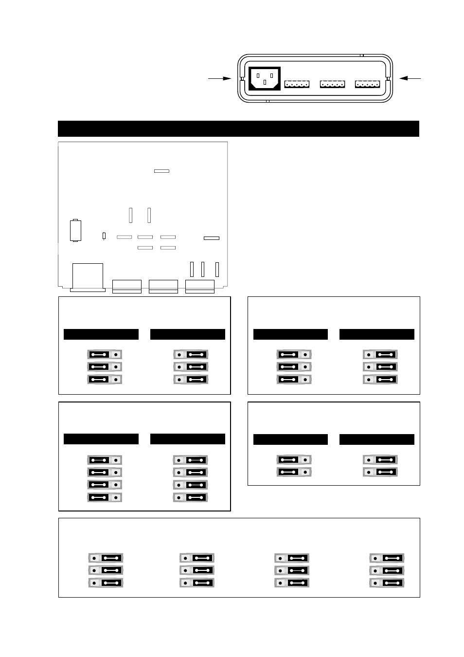
Factory setting
Settings
The LA-01 can through different settings
be adapted to a variety of running
conditions. To set the jumpers, open
the plastic case by placing and turning a
screw-driver between top and bottom at the rear of the case.
Warning! Do not open connected unit
J2 – J11
Selection of RS-232-C/V.24 or
J2 – J11
W1interface on channel 1, 2 and 3
J12/J13
Selection of V or Y function,
see block diagram
S1
Selection of power supply
115 V/230 V AC
J1
Connects protected ground
to signal ground.
CHANNEL 3
CHANNEL 2
CHANNEL 1
2 3
1
2 3
1
2 3
1
3 2 1
3 2 1
3 2 1
3 2 1
1
2
3
3
2
1
3
2
1
3
2
1
1
2
3
J13
S1
J1
J6
J10
J7
J8
J11
J12
J2
J3
J4
X4
X2
X1
115
230
RS-232-C/V.24 or W1,
channel 1
J3
J4
J2
RS-232-C/V.24
W1
J3
J4
J2
J3
J4
J2
RS-232-C/V.24
W1
J10
J11
J9
J13
J12
RS-232-C/V.24 or W1,
channel 2
J6
J7
J8
J5
J6
J7
J8
J5
J6
J7
J8
J5
1 2 3
1 2 3
1 2 3
1 2 3
1 2 3
1 2 3
1 2 3
1 2 3
RS-232-C/V.24 or W1,
channel 3
J10
J11
J9
RS-232-C/V.24
W1
J10
J11
J9
1 2 3
1 2 3
V or
Y function
J13
J12
V funktion
Y funktion
J13
J12
1 2 3
1 2 3