Switch settings, Cts controlled by – Westermo MA-19 User Manual
Page 3
9
6019-2001
F2
F1
S1
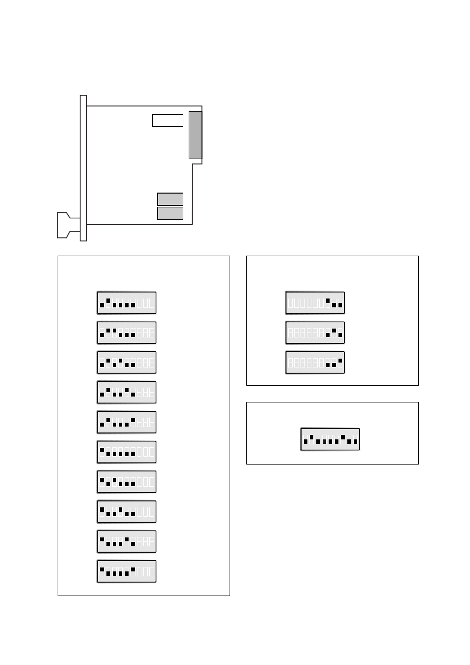
Switch settings
The MA-19 can through different switch settings be adapted to a variety of operating con-
ditions. The switches are located on the circuit board and have the following functions:
S1 1-6
Selection of signal activating trans-
mitter (carrier)
S1 7-9
Selection of signal controlling CTS
F1/F2
Fuse 100mA Fast
Transmitter
(carrier) activated by
Factory settings
Always active
S1
ON
1 2 3 4 5 6 7 8 9
AUX
S1
ON
1 2 3 4 5 6 7 8 9
SRS
S1
ON
1 2 3 4 5 6 7 8 9
RFR
S1
ON
1 2 3 4 5 6 7 8 9
RTS
S1
ON
1 2 3 4 5 6 7 8 9
DTR
S1
ON
1 2 3 4 5 6 7 8 9
DTR and AUX
S1
ON
1 2 3 4 5 6 7 8 9
DTR and SRS
S1
ON
1 2 3 4 5 6 7 8 9
DTR and RFR
S1
ON
1 2 3 4 5 6 7 8 9
DTR and RTS
S1
ON
1 2 3 4 5 6 7 8 9
CTS
controlled by
RTS
S1
ON
1 2 3 4 5 6 7 8 9
RTS
S1
ON
1 2 3 4 5 6 7 8 9
Always high
S1
ON
1 2 3 4 5 6 7 8 9
DCD
S1
ON
1 2 3 4 5 6 7 8 9