Connections – Westermo MA-29 User Manual
Page 10
Advertising
10
6029-2002
1
2 3 4 5
1
2
3
4
5
1
13
25
14
Receiver
1
R+
Receiver
2
R-
Transmitter
3
T+
Transmitter
4
T-
5
Shield
No.
I
2
103
TD/Transmitted Data
O
3
104
RD/Received Data
I
4
105
RTS/Request To Send
O
5
106
CTS/Clear To Send
O
6
107
DSR/Data Set Ready
–
7
102
SG/Signal Ground
O
8
109
DCD/Data Carrier Detect
I=Input O=Output on MA-29
Direction
Description
Description
Direction
Pin
no.
ITU-T V.24
Circuit no.
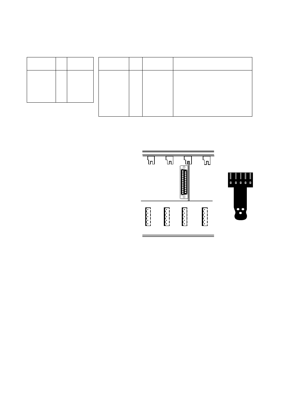
Connections
Line connection
(5-Position screw-terminal)
Terminal connection (DCE)
(RS-232-C/V.24/V.28, 25-position D-sub, female)
Section of rack RV-01 with
one MA-29 mounted.
Terminal connection to a 25-position D-sub
(female) connector on MA-29.
Line connection to a 5-position
detachable screw-terminal, which
is mounted on the male connector
located at the rear of RV-01.
Advertising