Block diagram – Westermo MD-21 User Manual
Page 8
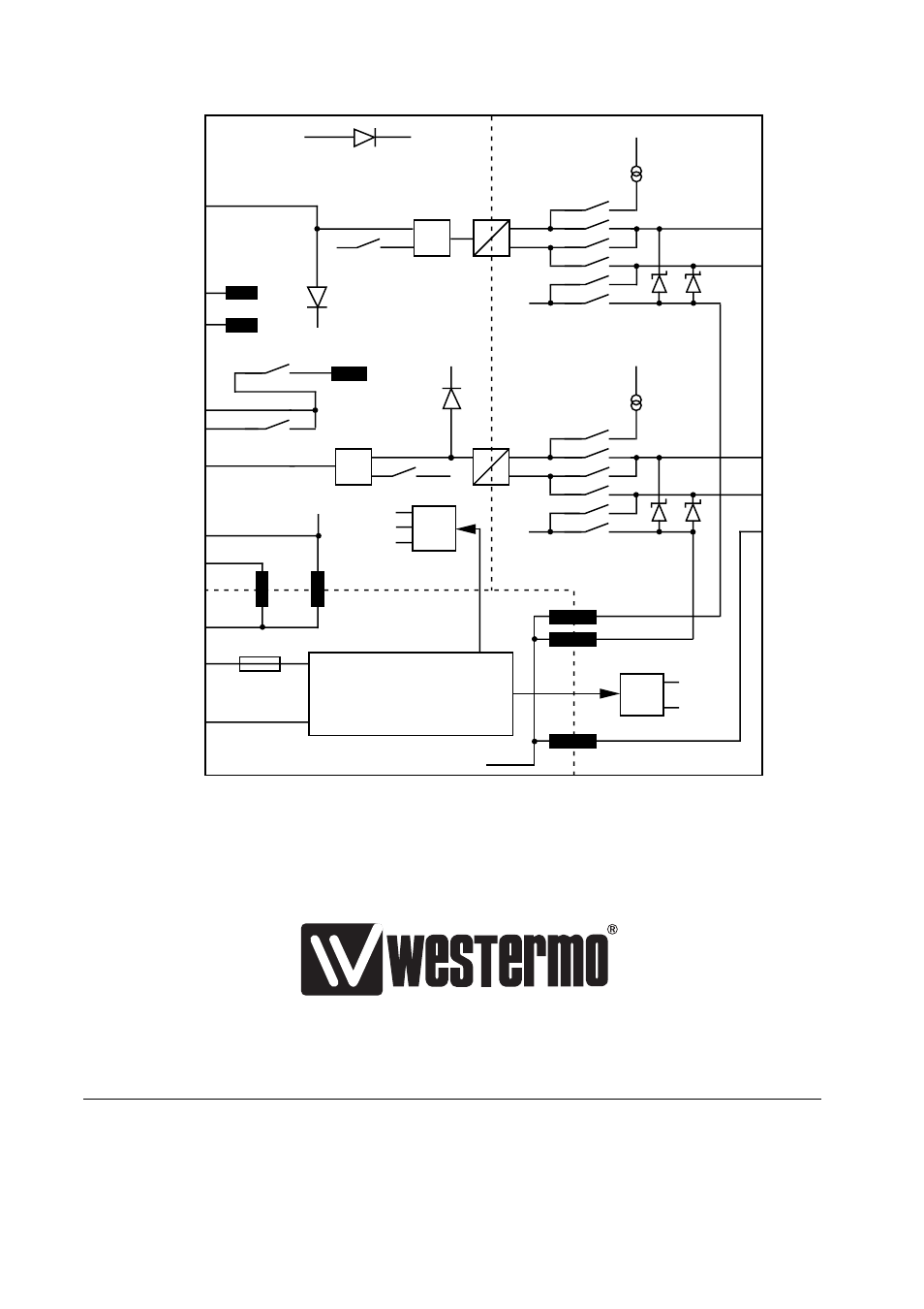
1) 0 Ω resistors R1, R48-R50 are normally not mounted.
2) Metal housing on D-sub is connected to PE if R is mounted.
R = R3 on the DC-mod and R1 on AC-mod.
Block diagram
V.24/RS-232
TD
DSR
OVB
DCD
CTS
RTS
RD
SG
+12V
0V
-12V
D-sub housing
PE
Power
supply
Insulated power supply
Line
T+
S4
20mA
PWR
F1
=1
=1
+24VB
+24VB
20mA
S3
3
4
1
2
5
3
6
1
8
7
4
3
S1
2
5
1,2)
R
R47
6
5
2
4
1
3
6
5
2
4
1
3
1
2
+
+
S1
T-
R+
+12V
+12V
+12V
TD
R-
Shield
PE
0VB
S1
RD
R48
R50
R49
1)
1)
OVB
+24VB
6151-2002
01.99
T
unaT
ryck
AB, Eskilstuna, Sweden
Westermo Teleindustri AB • S-640 40 Stora Sundby, Sweden
Phone +46 16 612 00 Fax +46 16 611 80
E-mail: [email protected] • Westermo Web site: www.westermo.se
Westermo Teleindustri AB have distributors in several countries,
contact us for further information.
Westermo Data Communications GmbH
Bruchsaler Straße 18, 68753 Waghäusel
Tel.: +49(0)7254-95400-0 • Fax.:+49(0)7254-95400-9
E-Mail: [email protected]
Westermo Data Communications Ltd
Solent Business Centre • Millbrook Road West
Millbrook, Southampton • SO15 0HW
Phone: +44(0)1703-704 611 • Fax.:+44(0)1703 702 682
E-Mail: [email protected]
Subsidiaries