0 functional description, 1 block diagram – Westermo MD-45 User Manual
Page 27
27
6157-2003
V.11/RS-422
RS-485
V.24/RS-232
3
4
A
B
TD LED
TD LED
3
TD
CTS
LED
S2:4
F1
0V
+5V
1
2
A’
B’
5
0V
RTS
CTS
RD
RD
LED
7
8
2
B
B
0V
SG
S1:6
Shield
DSR
6
+5V
5
S2:2
S2:1
S2:3
Power
supply
Insulated power supply
0V
+5V
B
+5V
Bus termination
0V
B
B
+5V
Bus termination
0V
B
B
A
A
A
RTS LED
MCU
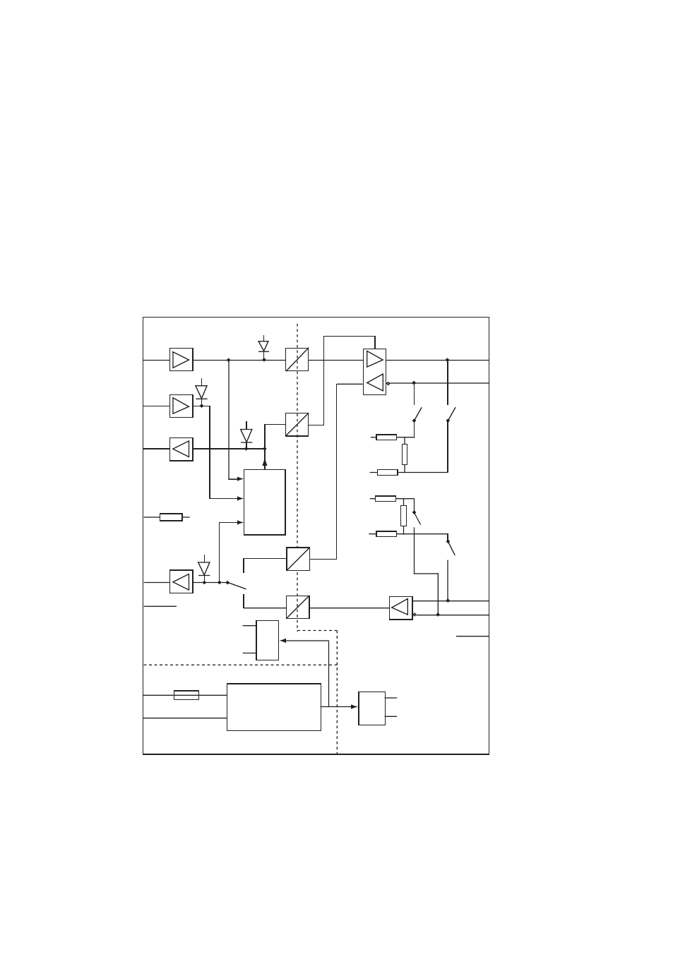
7.0 Functional description
When the converter is set to data-control mode the transmitter is activated by data on
TD (RS-232). The time the transmitter stays active corresponds to one character-time
and turning time for the set data rate and number of bits. If there is more data on TD
before the turning time is ended the transmitter stays active for additional one character.
In RTS-control mode the transmitter is activated by the RTS-signal. In this mode the
switches for data rate and number of bits has no effect. The LED indicators is controlled
by the data signals. The active termination secures that the signal level at the receiver is
in off-state (>0.2 Volts) when there is no data transmission. Full duplex is only possible if
RS-422 is used.
7.1 Block diagram