Line connection, Power budget, Attenuation in fibre cable – Westermo MX-69 User Manual
Page 3: Typical attenuation in connectors, Typical attenuation in splice
5
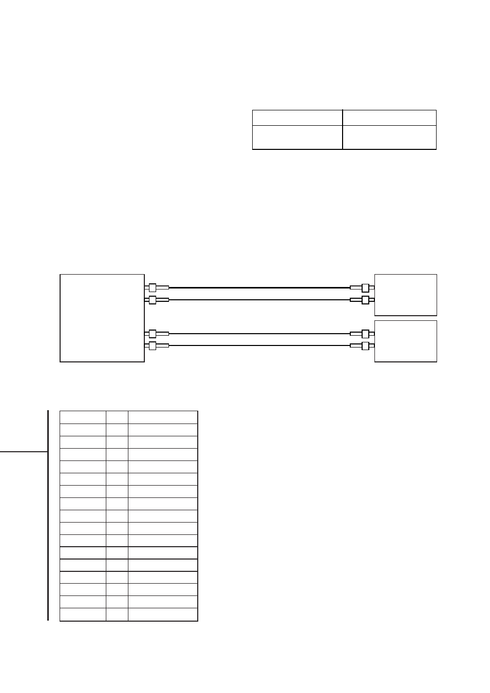
6119-2001
Tx
Rx
Interface 1
The signal ground (SG) is connected to pin:
4, 7, 10, 13, 14, 17, 20, 23
Channel 1–4
Rx
Tx
Channel 5–8
Channel 1–4
Channel 5–8
Rx
Tx
Tx
Rx
MX-69
2 x MX-61
Line connection
Direction Pin
Description
In
2
TxD channel 1
Out
15
RxD channel 1
In
3
TxD channel 2
Out
16
RxD channel 2
In
5
TxD channel 3
Out
18
RxD channel 3
In
6
TxD channel 4
Out
19
RxD channel 4
In
8
TxD channel 5
Out
21
RxD channel 5
In
9
TxD channel 6
Out
22
RxD channel 6
In
11
TxD channel 7
Out
24
RxD channel 7
In
12
TxD channel 8
Out
25
RxD channel 8
Power budget
Fibre (820nm)
Power budget
50/125
mm
3.7 dB
62,5/125
mm
7.5 dB
200
mm PCS
18 dB
Attenuation in fibre cable
The values below can differ depending on
quality and manufacturer of the fibre-optic
cable.
Typical attenuation
in connectors
0.2–0.4 dB
Typical attenuation in splice
Svetsad
0.1 dB
Mekanisk
0.2 dB
Fibre
Attenuation at 820nm
50/125 µm
3.0 dB/km
62.5/125 µm
3.5 dB/km