Synchronous mode odw-630-f2, Example, Sw:1 sw:2 transmitter on – Westermo ODW-630-F2 User Manual
Page 20: 6 ms, 416 µs, 208 µs, 104 µs, 52 µs, 26 µs, 13 µs
20
6651-22651
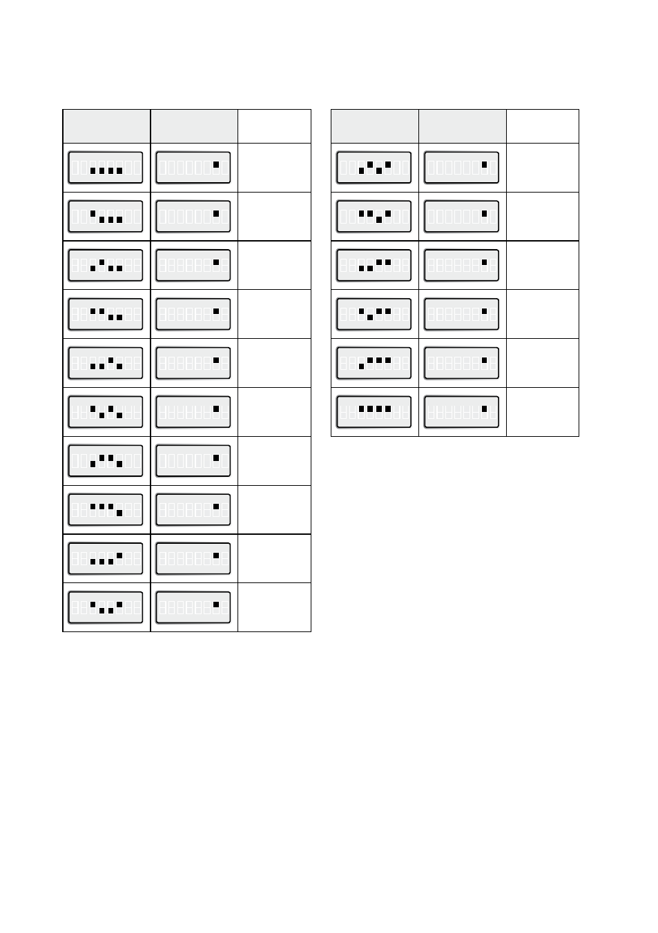
SW:1
SW:2
Transmitter
ON
ON
1 2 3 4 5 6 7 8
ON
1 2 3 4 5 6 7 8
1.6 ms
ON
1 2 3 4 5 6 7 8
ON
1 2 3 4 5 6 7 8
416 µs
ON
1 2 3 4 5 6 7 8
ON
1 2 3 4 5 6 7 8
208 µs
ON
1 2 3 4 5 6 7 8
ON
1 2 3 4 5 6 7 8
104 µs
ON
1 2 3 4 5 6 7 8
ON
1 2 3 4 5 6 7 8
52 µs
ON
1 2 3 4 5 6 7 8
ON
1 2 3 4 5 6 7 8
26 µs
ON
1 2 3 4 5 6 7 8
ON
1 2 3 4 5 6 7 8
13 µs
ON
1 2 3 4 5 6 7 8
ON
1 2 3 4 5 6 7 8
8.6 µs
ON
1 2 3 4 5 6 7 8
ON
1 2 3 4 5 6 7 8
4.3 µs
ON
1 2 3 4 5 6 7 8
ON
1 2 3 4 5 6 7 8
4 µs
Synchronous mode ODW-630-F2
RS-485 transmitter on-time after last data transition
SW:1
SW:2
Transmitter
ON
ON
1 2 3 4 5 6 7 8
ON
1 2 3 4 5 6 7 8
2.6 µs
ON
1 2 3 4 5 6 7 8
ON
1 2 3 4 5 6 7 8
2.1 µs
ON
1 2 3 4 5 6 7 8
ON
1 2 3 4 5 6 7 8
2 µs
ON
1 2 3 4 5 6 7 8
ON
1 2 3 4 5 6 7 8
1 µs
ON
1 2 3 4 5 6 7 8
ON
1 2 3 4 5 6 7 8
500 ns
ON
1 2 3 4 5 6 7 8
ON
1 2 3 4 5 6 7 8
300 ns
Example:
The data speed in a particular application is
250 kbit/s.
Calculate the maximum data transition time:
1/250 x 10
3
= 4 x 10-
6
= 4 µs.
Using dip-switches 1:3 – 1:6, set the transmitter
on time to the closest higher value, e.i. 4.3 µs.
Note: Selecting a transmitter on time that is
shorter than the data transition time will result
in corrupted data.