Power external, Psu fail – Westermo TR-36 User Manual
Page 24
Advertising
24
6614-2202
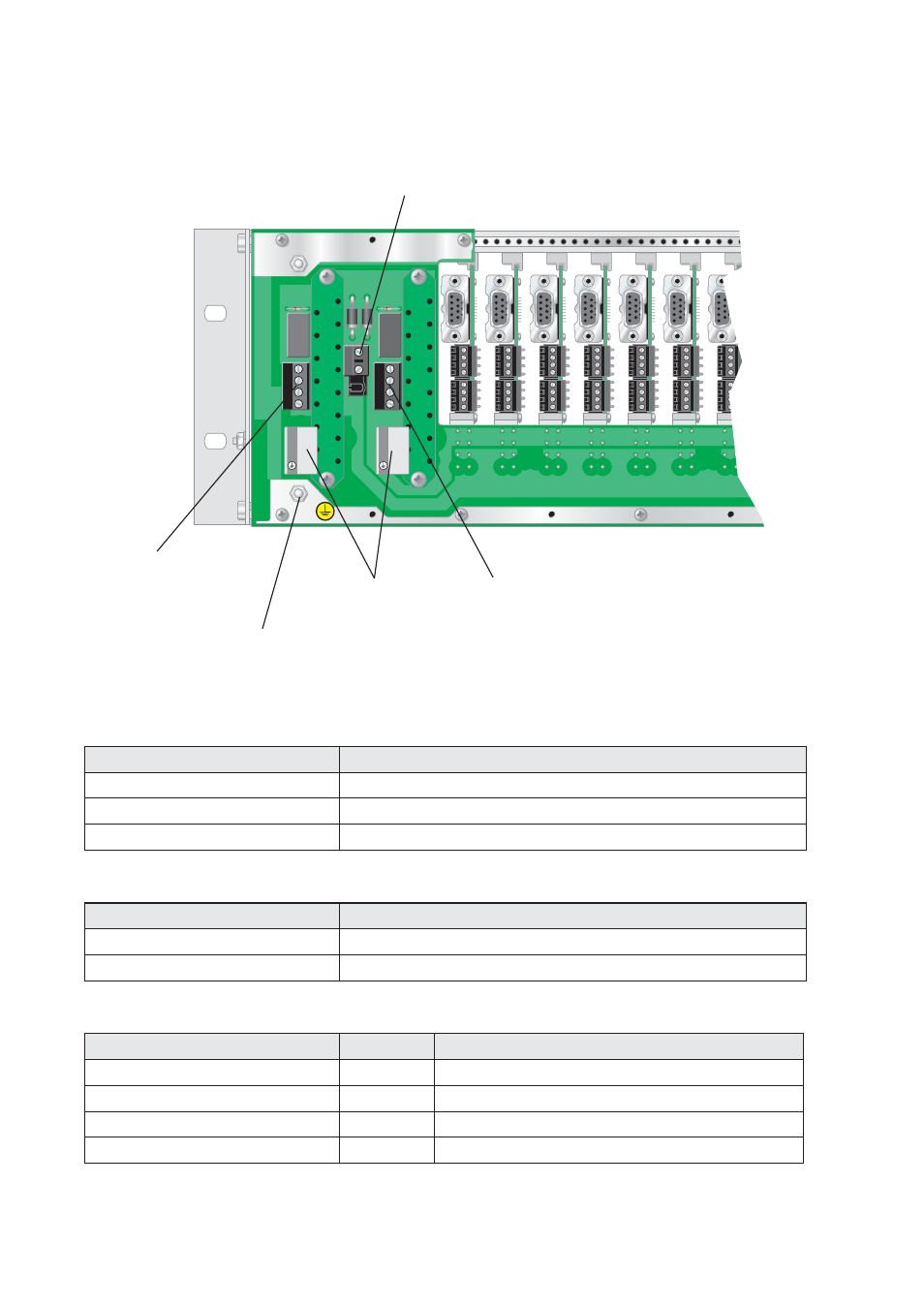
D2
D1
X4
P2
X3
P1
4
3
2
1
4
3
2
1
2
1
L
N
L
N
Extern 24 VDC
PS-20 HV
Protective Earth
PSU Fail
PSU Fail
Rear connections
TR-36, RV-07 and Power Supply
Power PS-20
Connection
Description
3-pos screw terminal, L
Line
3-pos screw terminal, N
Neutral
3-pos screw terminal, PE
Protective Earth, Not Connected Internally
Power External
Connection
Description
2-pos screw terminal, 1
0 VDC
2-pos screw terminal, 2
+24 VDC
PSU Fail
Connection
Direction Description
4-pos screw terminal no. 1
–
C – Common
4-pos screw terminal no. 2
–
NO – Normally Closed
4-pos screw terminal no. 3
–
NC – Normally Open
4-pos screw terminal no. 4
–
No Used
Advertising