User’s manual – X-Treme Audio Monitor Line User Manual
Page 3
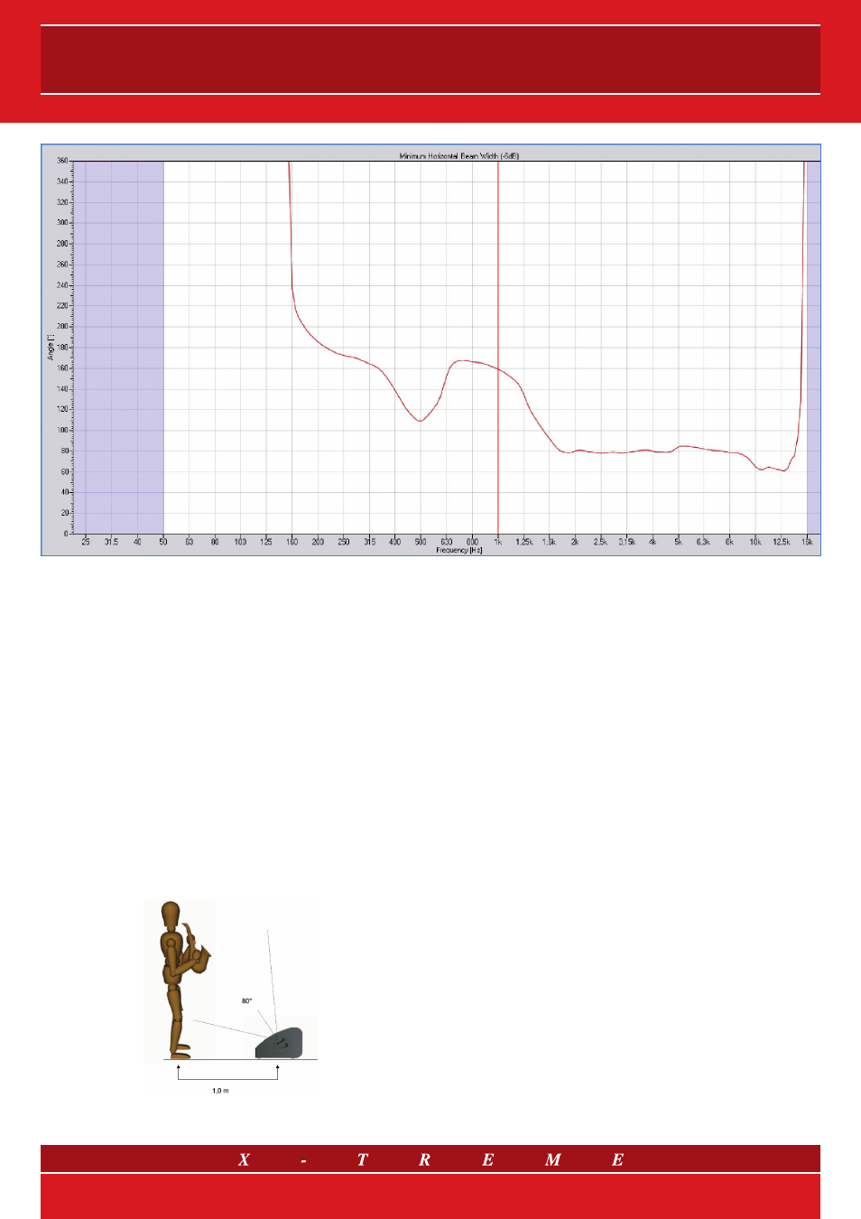
3. DIRECTIVITY
The chart above shows the amplitude of the output sound beam in re-
lation to the frequency of the
XTMON12 (passive), measured at Sound
Corporation’s R&D laboratory in virtually anechoic conditions (calcu-
lation of the impulse response and rejection of reflections). The illustra-
tion shows the angle at whose boundaries the sound pressure drops
by 6 dB from the on-axis value in relation to the frequency. The width
of the vertical beam is actually quite similar to the horizontal beam
shown because of the coaxial system of transducers. The entire band
covered by the tweeter (that is above 1800 Hz - the crossover fre-
quency) has a uniform beam of 80° (conversely, some lobing is inevita-
ble in the range covered by the woofer and is quite generalised, given
by the ratio between the diameter of the cone and the wavelength of
the frequency in question). This can be heard quite clearly while listen-
ing: the continuation of the timbre and the clarity of the sound within
the entire established emission angle are striking.
The angle of the transducer surface (31°) makes for excellent listen-
ing quality at a distance of about one metre for a person of average
height, aligned with the transducer. Due to the 80° angle of dispersion,
the sound will remain clear and intelligible up to a distance of 4.5 m.
4. GUIDELINES FOR USING PASSIVE MONITORS:
STANDARDS AND PRECAUTIONS
The
Monitor Line is a series of passive and amplified products. The
passive versions have passive crossover filters with equalisation and
fader cells, designed so the transducer channels can provide a uni-
form frequency response. This makes it possible to achieve excellent
sound quality with the XTMON12 and XTMON15 speakers without the
need for an external processor: simply plug and go! In particular, the
passive crossovers of the XTMON12 and XTMON15 have frequency
fading on very tight bands (notch) on the critical frequencies due to the
Larsen effect when microphones are being used. Using processors,
however, can be practical when it is vital to safeguard the quality of the
sound as well as to protect the speakers and to exploit their maximum
potential: a crucial issue for sound professionals. The amplifiers’ input
voltage has to be controlled to ensure there will be no damage to the
speaker’s passive components with signals that are too powerful or
generally unsuitable for an acoustic transducer: the following para-
graph explains how and why.
It is not possible to protect the speakers a priori from harmful phenom-
ena that originate within the amplifier itself by adjusting the amplifier
input signal: if an amplifier malfunction leads to the supply of direct cur-
rent or ultra low frequency, this can be harmful for the transducers re-
gardless of the input signal. Similarly, severe voltage peaks caused by
switching the equipment (ON or OFF) upstream to the amplifiers, when
the amplifiers are already ON, may cause damage to the transducers:
when you supply a Sound Reinforcement system, it is crucial to switch
on the amplifiers only once the mixer and the control electronics are
up and running (and have stabilised). Follow the sequence in reverse
order when shutting down the system, switching off the power ampli-
fiers first.
Proper control and maintenance of a sound system are as impor-
tant as following the correct sequence when switching devices in the
sound network on and off.
3/7