Page 42
Single- and Dual-Blower Continuous Vacuum/Pressure Systems
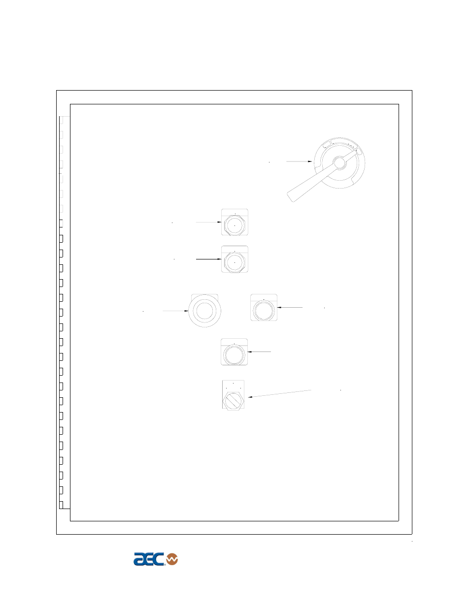
Figure 12
Typical SVP Control Panel Layout
42079Q91
F
OF
_
0
ON
POWER switch
PURGE switch
START switch
PURGE
Silo selector switch
R
POWER
A
START
STOP switch
1
2
SILO
Disconnect
PURGE STOP switch