Airaid 450-264C User Manual
Installation instructions, Component identification, For part numbers
Installation Instructions
For Part Numbers:
450-264C 700-461 Airaid Oiled Media Filter
451-264C 701-461 SynthaMax Dry Media Filter - Red
452-264C 702-461 SynthaMax Dry Media Filter - Black
453-264C 703-461 SynthaMax Dry Media Filter - Blue
2011-14 Ford Mustang GT
5.0L V8
2. A) Loosen the hose clamps on the factory intake
tube B) Squeeze the spring clamp and disconnect the
resonator from the air intake tube. C) Carefully depress
the hose lock tab, and disconnect the crank case breather
line and the brake aspirator line if equipped, (AT models
only). D) Remove the factory intake tube.
3. A) Disconnect the wir ing har ness fr om the Mass Air
Flow sensor (MAF). Car efully pr y the har ness anchor
from the air box using a screwdriver. B) Separate the
resonator tube from the Air box lid. C) Using a 10mm
socket, remove the bolt securing the air box to the inner
fender and remove the air box assembly. This bolt will be
reused in step 10.
4. Remove the resonator assembly from the vehicle.
A. Slide the hanger off of the str ut tower tab.
B. Remove the 6mm bolt secur ing the diaphr agm
body to the inner fender.
Slide the resonator tubing out of the firewall and set the
assembly aside. It will not be reused.
5. Insert the Fire Wall Plug (#16) into the resonator hole. 6. Using the supplied Torx bit, (#19) remove the MAF
sensor from the factory airbox and transfer it into the
Airaid Tube assembly (#2).
Install the MAF sensor using two provided 8-32x3/8”
screws (#10).
Do Not Use The Factory Screws!
8. Install the filter adapter (#4) using three 1/4-20 button
head bolts (#9), and Fat Washers (#8) into the Airaid
Cool Air Box (CAB) (#3) as shown.
INSTALL NOTE:
If you are installing this kit on a vehicle equipped
with a
Power Dome Hood with Heat Extractors
we suggest the use of our
optional AIRAID pre-filter (Part #799-469) to give an added layer of protection
from the elements.
7. Install the Grommets and Fittings into the Airaid Intake
Tube (#2): A) All models will require the use of the 5/8”
Fitting (#15) and the 5/8”Grommet (#12). B) Automatic
transmission equipped vehicles will also use the 3/8” Fit-
ting (#14) and 3/8” Grommet (#11). Manual transmission
vehicles will not need the 3/8” components and will use
the Blind Grommet(#13
9. Transfer the factory air box mounting grommets. A)
Locate and remove the Two Lower air box mounting
grommets, and install them in the inner fender. B) Re-
move the Upper air box mounting grommet and steel
sleeve, and re-install into the Airaid CAB.
A.
C.
A.
B.
C.
A.
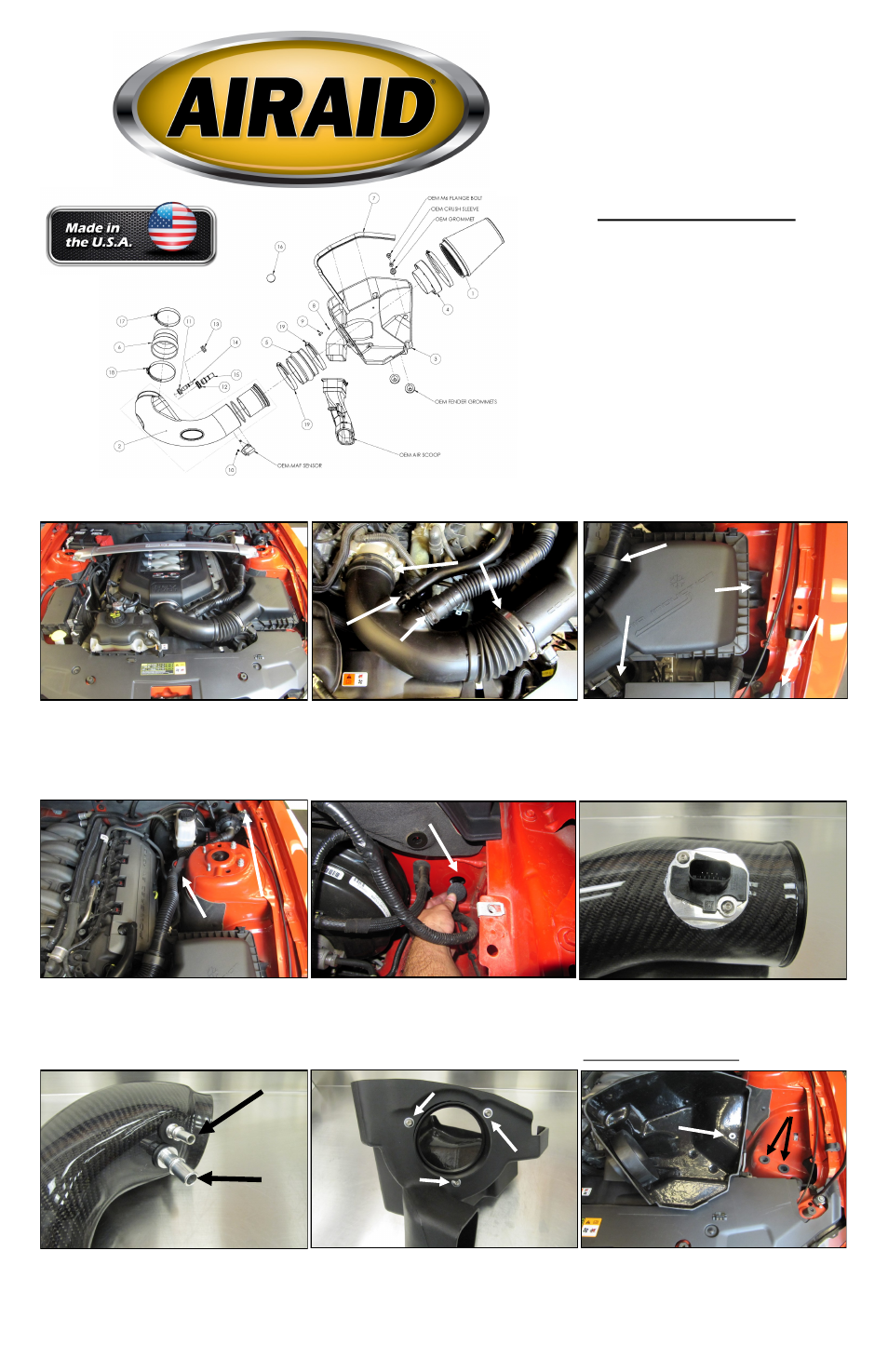
Component Identification
1.
Airaid Premium Filter
1
2.
Airaid Intake Tube Assembly
1
3.
Cool Air Box
1
4.
Filter Adapter
1
5.
Silicone Hump Hose
1
6.
Silicone Coupler
1
7.
Weather Strip 25"
1
8.
1/4” Flat Washer
x3
9.
¼-20 x 1/2” Button Head Cap Screw
x3
10.
8-32 x 3/8” Button Head Cap Screw
x2
11.
3/8” Grommet
x1
12.
5/8” Grommet
x1
13.
Blind Grommet
x1
14.
3/8 Aluminum Fitting
x1
15.
5/8” Aluminum Fitting
x1
16.
Firewall Plug
x1
17.
#56 Hose Clamp
x1
18.
#64 Hose Clamp
x3
19.
T-20 Torx Bit
x1
Disconnect The Negative Battery Terminal!
1. If so equipped, remove the strut tower brace, then re-
move the engine cover by simply lifting it up, and set
aside.
B
B.
A.
B.
A.
B.
Full color instructions can be viewed on our web site at Airaid.com. Use the Product Search function to find your part number, and click View Details.